POWER CON
PCON-CB/LC
15
11) Brake Release Switch (BK RLS/NOM)
For the actuator equipped with a brake, the switch is used to release the brake forcibly.
BK RLS ···· Brake forcible release
NOM········ Normal operation (brake is activated)
12) Power Supply Connector [Refer to 2.3.1 Wiring Layout of Power Supply Connector]
It is the connector for the power supply (for controller control power, actuator driving and
brake control power) and for the input of emergency status signal.
13) Fan Unit
It is a forced cooling unit dedicated for PCON-CFB Type.
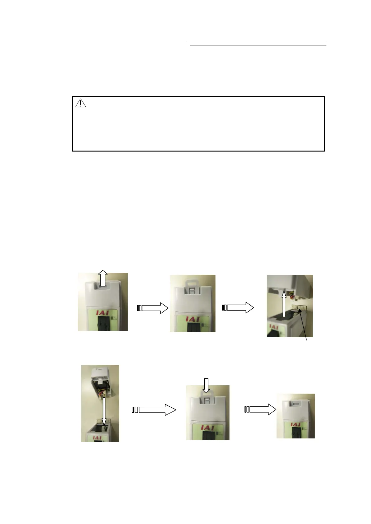
14) Fan Unit Desorption Lever
When fixing to a control box and replacing the fan unit, pull the lever up and the fan unit can
be taken out. When fixing, put the unit back on, and when replacing, attach a new unit, and
push the lever down to affix the unit.
How to Detach
How to Attach
Warning : Always set the switch to “NOM” in normal operation.
(Make sure the opportunity to put the switch to RLS side is the minimum
and is limited to when startup and adjustment. Make certain to set the
switch to NOM side in normal use.)
The brake would not work even with the servo OFF condition if the switch is
on the RLS side. In the vertical oriented mount, the work may drop and
cause an injury or the work to be damaged.
φ5 hole to hold main body
Match the connectors
to attach
Push in the lever till
making a click noise
 Loading...


