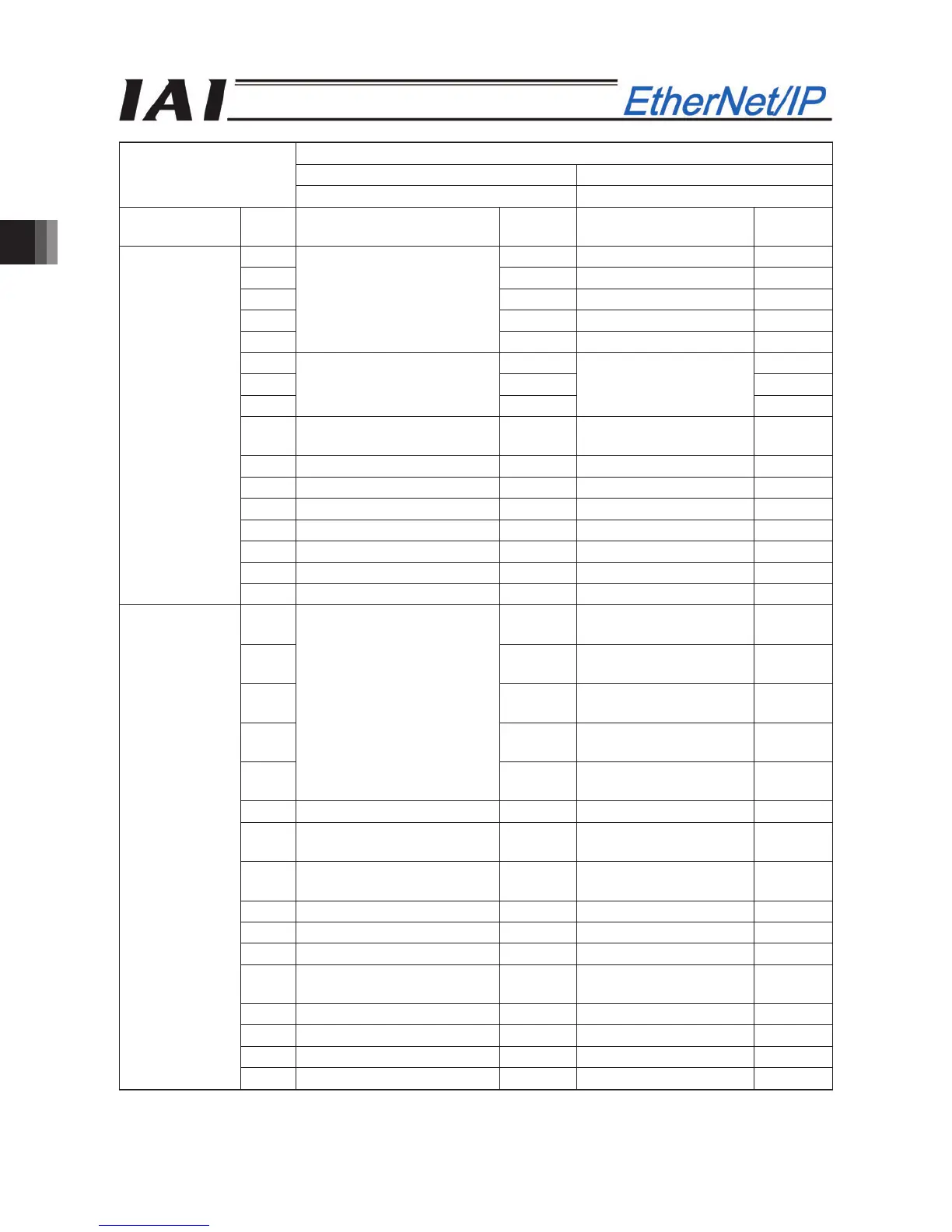
3. SCON-CA
100
Setting of parameter No. 25
Force control mode 1 Force control mode 2
6 7
Category
Port
No.
Signal name Symbol Signal name Symbol
0 PC1 Start position 0 ST0
1 PC2 Start position 1 ST1
2 PC4 Start position 2 ST2
3 PC8 Start position 3 ST3
4
Command position number
PC16 Start position 4 ST4
5 - -
6 - -
7
Cannot be used.
-
Cannot be used.
-
8
Load cell calibration
command
CLBR
Load cell calibration
command
CLBR
9 Forced brake release BKRL Forced brake release BKRL
10 Operation mode RMOD Operation mode RMOD
11 Home return HOME Home return HOME
12 Pause *STP Pause *STP
13 Positioning start CSTR Cannot be used. -
14 Reset RES Reset RES
PLC output
SCON-CA input
15 Servo ON command SON Servo ON command SON
0 PM1
Completed position
number 0
PE0
1 PM2
Completed position
number 1
PE1
2 PM4
Completed position
number 2
PE2
3 PM8
Completed position
number 3
PE3
4
Completed position number
PM16
Completed position
number 4
PE4
5 Torque level status TRQS Torque level status TRQS
6
Load output judgment
status
LOAD
Load output judgment
status
LOAD
7
Load cell calibration
complete
CEND
Load cell calibration
complete
CEND
8 Position zone PZONE Position zone PZONE
9 Operation mode RMDS Operation mode RMDS
10 Home return complete HEND Home return complete HEND
11 Positioning complete signal PEND
Positioning complete
signal
PEND
12 Operation ready SV Operation ready SV
13 Emergency stop *EMGS Emergency stop *EMGS
14 Alarm *ALM Alarm *ALM
SCON-CA
output
PLC input
15 Battery alarm *BALM Battery alarm *BALM
The symbol with a * mark shows the ON signal in normal condition.
The signal described as “Unavailable” is not controlled.(ON/OFF is undefined.)