2. ACON, PCON
44
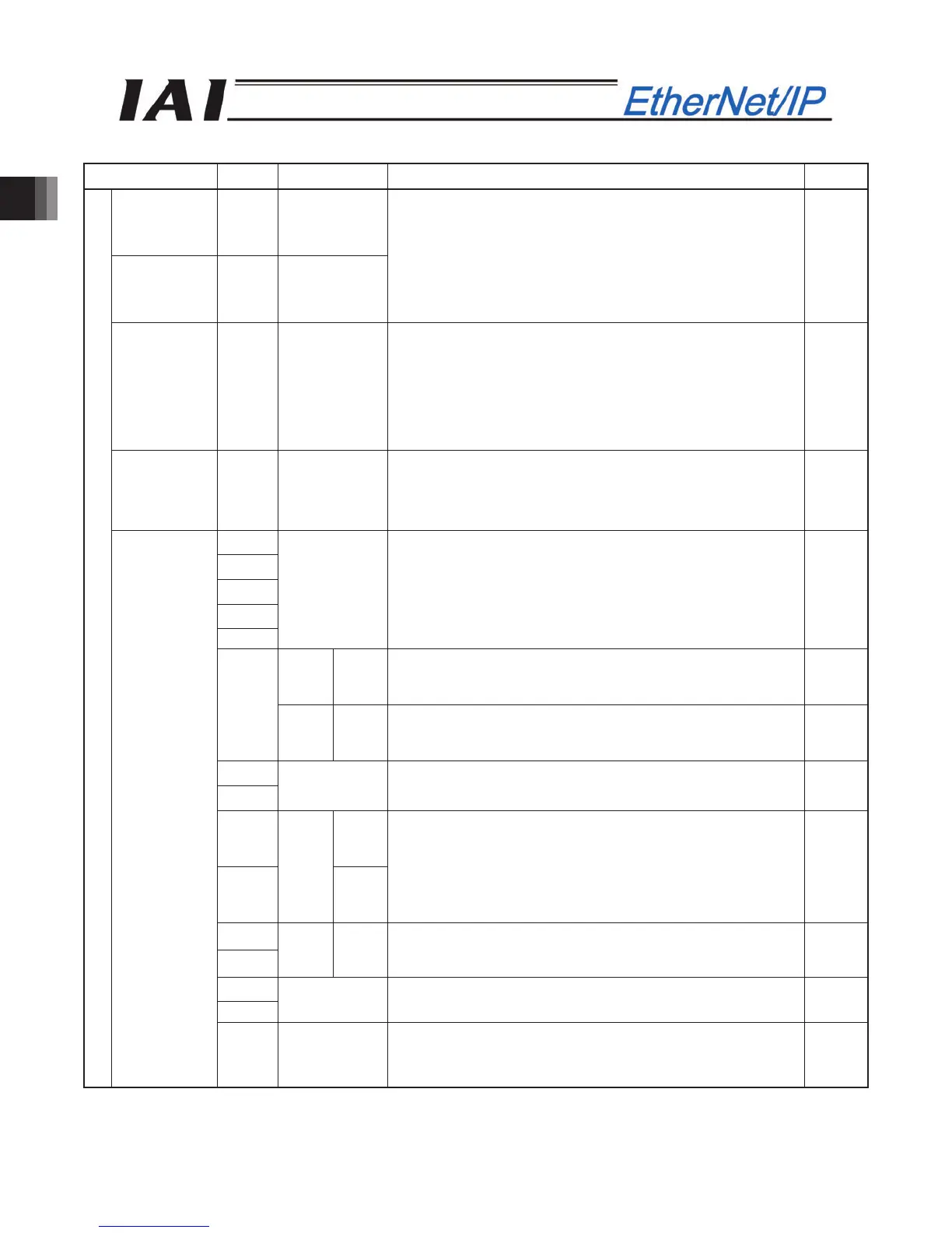
(* “ON” in the table shows the corresponding bit of “1” and “OFF” shows “0”.)
Address Bit Symbol Function Details
Acceleration
16-bit
data
-
Deceleration
16-bit
data
-
16-bit integer
Specify the acceleration and deceleration at which to move
the actuator.
The unit is 0.01G and settable range is 1 to 300.
(Example) When it is “0.30G”, set it as “30”.
If a move command is issued by specifying “0” or any value
exceeding the maximum acceleration or deceleration, an
alarm will occur.
2.8 (3)
Pressing
current-limiting
value
16-bit
data
-
16-bit integer
Specify the current- limiting value to be used during pressing
operation. The allowable specification range is 0 (0%) to 255
(100%).
The actual settable range varies depending on each actuator.
(Refer to the catalog or operation manual for the actuator.)
If a move command is issued by specifying a value exceeding
the maximum pressing current, an alarm will occur.
2.8 (3)
Load current
threshold
16-bit
data
-
16-bit integer
Set the current threshold in this register when whether or not
the load current exceeds the threshold is judged.
The allowable specification range is 0 (0%) to 255 (100%). If
threshold judgment is not required, enter “0”.
2.8 (3)
b15
b14
b13
b12
b11
-
Unavailable -
ACON
-
Unavailable
-
b10
PCON SMOD
Stopping control mode: When this signal is ON, servo control
is performed during stopping.
2.6.7
(28)
b9
b8
-
Unavailable
-
b7 MOD1
b6
ACON
MOD0
Acceleration / deceleration mode:
When both signals are OFF, the trapezoid pattern mode is
selected.
When one signal is OFF and the other signal is ON, the
S-motion mode is selected. When one signal is ON and the
other signal is OFF, the primary delay filter mode is selected.
2.6.7
(29)
b7
b6
PCON
-
Unavailable -
b5
b4
-
Unavailable -
PLC output
Control signal
1
b3 INC
Incremental Command:
Absolute position commands are issued when this signal is
OFF, and incremental position commands are issued when
the signal is ON.
2.6.7
(24)