2. ACON, PCON
41
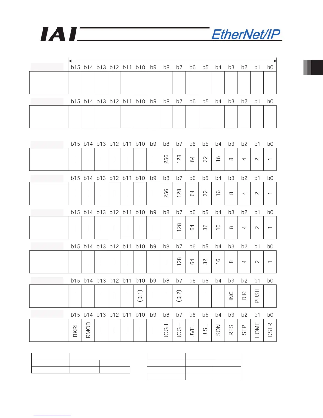
Address (* “n” indicates the first output address of each axis.)
When the zone boundary is shown using the negative figure, it is expressed using the complement of 2.
(*1) Signal assignment for b10 of n+28, n+29 (*2) Signal assignment for b7 and b6 of n+28, n+29
Symbol Symbol
Controller ACON PCON Controller ACON PCON
b10 - SMOD b7 MOD1 -
b6 MOD0 -
(*3) This is a dedicated function for PCON controllers. It is not available with ACON controllers.
1 word = 2 b
tes =16 bits
Control
signal 2
Acceleration
Deceleration
Pressing
current-limiti
ng value
Load current
threshold
(*3)
Control
signal 1
n+28, n+29
n+26, n+27
n+24, n+25
n+22, n+23
n+20, n+21
n+18, n+19
n+16, n+17
n+30, n+31