2. ACON, PCON
42
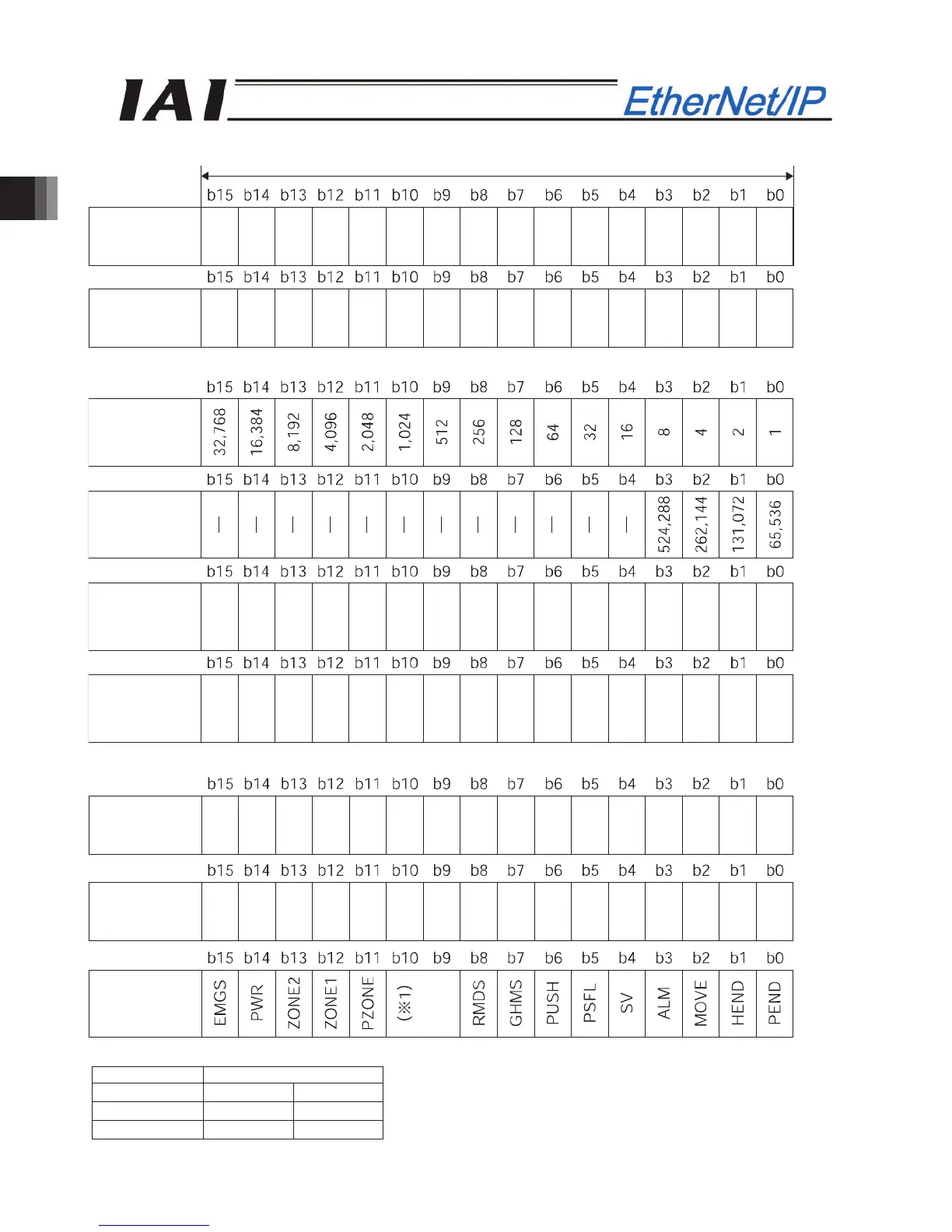
PLC input
Address (* “n” indicates the first input address of each axis.)
When the current position is shown using the negative figure, it is expressed using the complement of 2.
When the current speed is shown using the negative figure, it is expressed using the complement of 2.
(*1) Signal assignment for b10 and b9 of n+30, n+31
Symbol
Controller ACON
PCON
b10 -
LOAD
b9 -
TRQS
Current
position
lower word
1 word = 2 bytes =16 bits
n+0, n+1
Current
position
(upper word)
n+2, n+3
Command
current
lower word
n+4, n+5
Command
current
u
er word
n+6, n+7
Current
speed
(lower word)
n+8, n+9
Current
speed
(upper word)
n+10, n+11
Alarm code
n+12, n+13
Unavailable
n+14 ~ n+29
Status signal
n+30, n+31