2. ACON, PCON
38
2.6.5 Full Direct Value Mode (Number of Occupied Bytes: 32)
This is the operation mode with all the values (target position, speed, etc.) set up directly using values from
PLC. Set each value in the I/O area.
The robot cylinder's effective main functions that can be controlled using this mode, are as shown in the
following table.
ROBO cylinder function
{: Direct control
x: Disable
Home-return operation
{
Positioning operation
{
Speed and acceleration / deceleration
setting
{
Pitch feed (inching)
{
Pressing operation
{
Speed change during the movement
{
Operation at different acceleration and
deceleration
{
Pause
{
Zone signal output
{
PIO pattern selection x
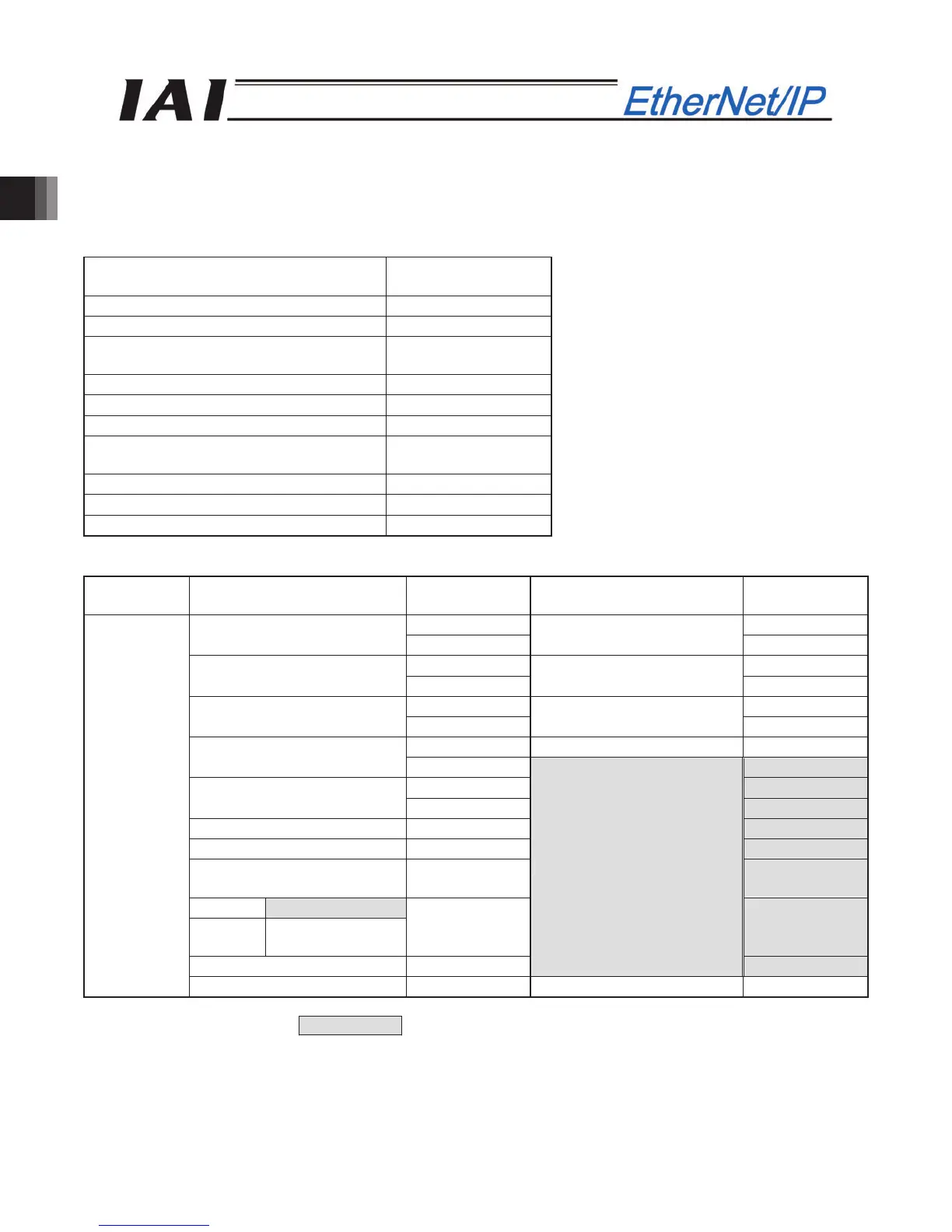
(1) PLC address configuration (* "n" indicates the first address of each axis.)
Parameter
No.84
ACON/PCON input register
PLC output
address (bytes)
ACON/PCON output register
PLC input
address (bytes)
n, n+1 n, n+1
Target position
n+2, n+3
Current position
n+2, n+3
n+4, n+5 n+4, n+5
Positioning band
n+6, n+7
Command current
n+6, n+7
n+8, n+9 n+8, n+9
Speed
n+10, n+11
Current speed
n+10, n+11
n+12, n+13 Alarm code n+12, n+13
Zone boundary +
n+14, n+15
n+14, n+15
n+16, n+17 n+16, n+17
Zone boundary -
n+18, n+19
n+18, n+19
Acceleration n+20, n+21 n+20, n+21
Deceleration n+22, n+23 n+22, n+23
Pressing current-limiting
value
n+24, n+25
n+24, n+25
ACON Occupied area
PCON
Load current
threshold
n+26, n+27
n+26, n+27
Control signal 1 n+28, n+29
Occupied area
n+28, n+29
3
Control signal 2 n+30, n+31 Status signal n+30, n+31
(Note) The areas denoted by Occupied area cannot be used for any other purpose.
Also, exercise caution to avoid node address duplication.