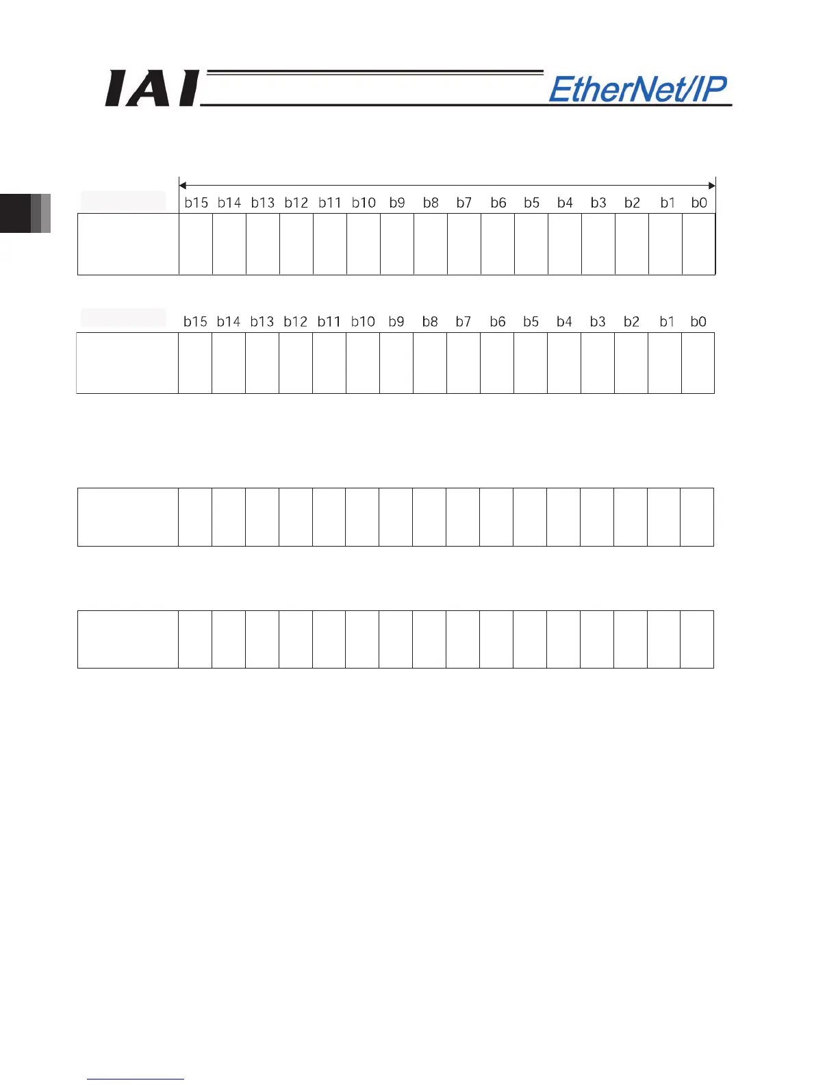
EasyManuals Logo

IAI pcon User Manual

Default Icon
216 pages
To Next Page IconTo Next Page
To Previous Page IconTo Previous Page
Page #136 background imageLoading...
Page #136 background image
3. SCON-CA
130
PLC input
Address (* “n” indicates the node address of each axis.)
When the current position is shown using the negative figure, it is expressed using the complement of 2.
b15 b14 b13 b12 b11 b10 b9 b8 b7 b6 b5 b4 b3 b2 b1 b0
Completed
position
number
PM512
PM256
PM128
PM64
PM32
PM16
PM8
PM4
PM2
PM1
b15 b14 b13 b12 b11 b10 b9 b8 b7 b6 b5 b4 b3 b2 b1 b0
Status signal
EMGS
PWR
CEND
ZONE1
PZONE/
ZONE2
LOAD
TRQS
RMDS
BALM
PUSHS
PSFL
SV
ALM
MOVE
HEND
PEND
Current
position
(lower word)
Current
position
(upper word)
1 word = 2 bytes =16 bits
n+0n+1
n+2n+3
n+2, n+3
n+0, n+1
n+4, n+5
n+6, n+7

Table of Contents

Other manuals for IAI pcon

Questions and Answers:

Question and Answer IconNeed help?

Do you have a question about the IAI pcon and is the answer not in the manual?

IAI pcon Specifications

General IconGeneral
Number of Axes1-4
ManufacturerIAI
CategoryController
Power Supply24 VDC
ProgrammingPC software
Communication InterfaceRS-232, RS-485
DimensionsVaries by model
Communication ProtocolsRS-232

Related product manuals