3. SCON-CA
136
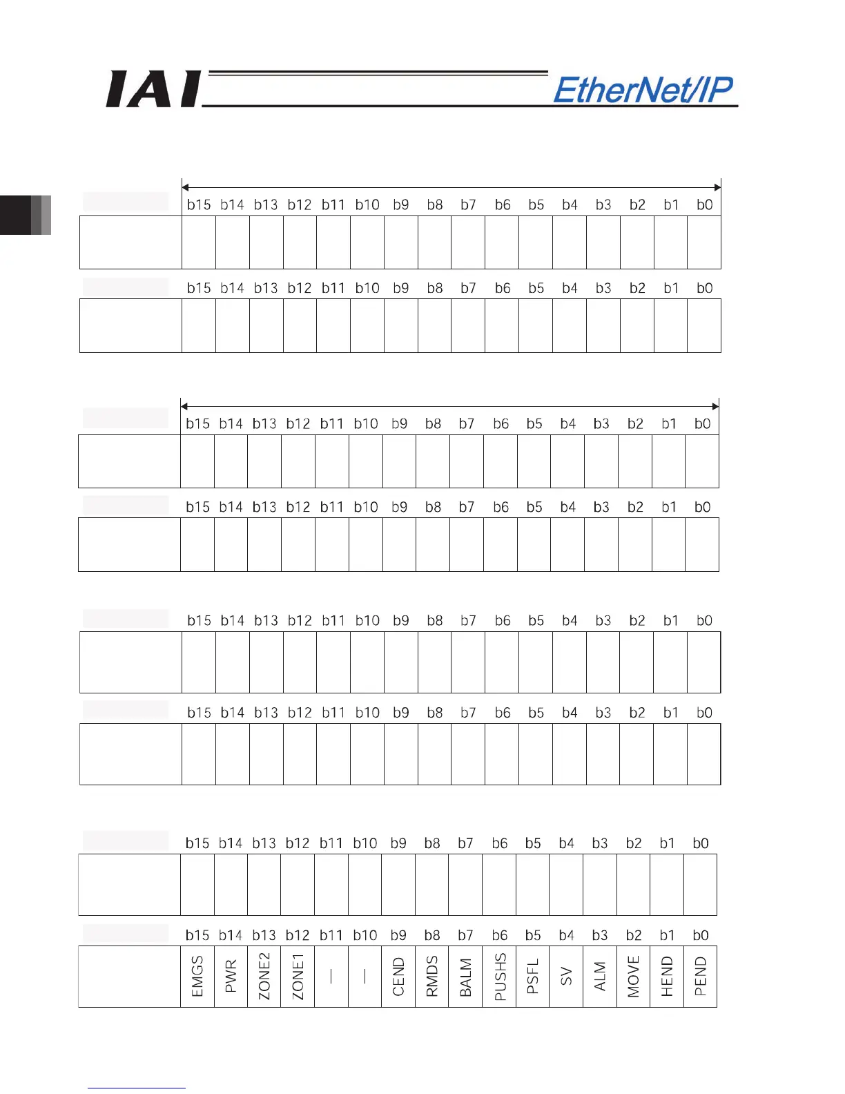
PLC input
Address (* “n” indicates the node address of each axis.)
When the current position is a negative figure, it is expressed using the complement of 2.
When the force feedback data is a negative value, it is expressed using the complement of 2.
When the current speed is a negative value, it is expressed using the complement of 2.
Current speed
lower word
Current speed
(upper word)
n+8ࠊn+9
n+10ࠊn+11
n+10, n+11
n+8, n+9
1 Word = 2 b
tes =16 bits
Force
feedback data
(lower word)
Force
feedback data
(upper word)
n+4ࠊn+5
n+6ࠊn+7
n+6, n+7
n+4, n+5
1 word = 2 b
tes =16 bits
Current
position
(lower word)
Current
position
(upper word)
n+0ࠊn+1
n+2ࠊn+3
n+2, n+3
n+0, n+1
Alarm code
Status signal
n+12ࠊn+13
n+14ࠊn+15
n+12, n+13
n+14, n+15