2. ACON, PCON
27
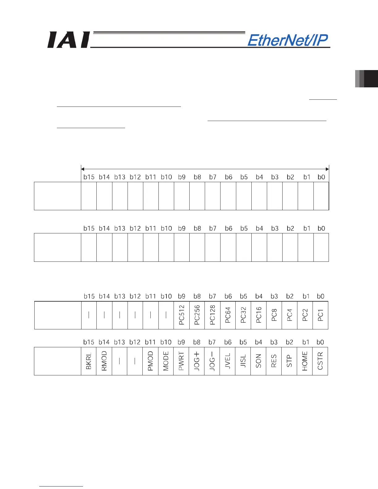
(2) I/O signal allocation for each axis
The I/O signals of each axis consist of four input words (4 words = 8 bytes) and four output words in the I/O
areas.
z The control signals and status signals are ON/OFF signals in units of bit.
z The target position and current position are expressed using 2 words (32 bits) binary data. The figures
from –999999 to +999999 (Unit: 0.01mm) can be set in PLC. However, set the position data within the
soft stroke range (0 to effective stroke length) for the actuator concerned.
z The specified position No. and completed position No. are expressed using 1-word (16 bits) binary data.
The figures from 0 to 767 can be set in PLC. However, set the position No. for which the operation
conditions have been set in advance using the PC software or teaching tools.
PLC output
Address (* "n" indicates the first output address of each axis.)
When the target position is shown using the negative figure, it is expressed using the complement of 2.
1 word = 2 bytes =16 bits
Target position
lower word
Target position
u
er word
n+2, n+3
n+0, n+1
Specified
position
number
Control signal
n+4, n+5
n+6, n+7