2. ACON, PCON
46
(* “ON” in the table shows the corresponding bit of “1” and “OFF” shows “0”.)
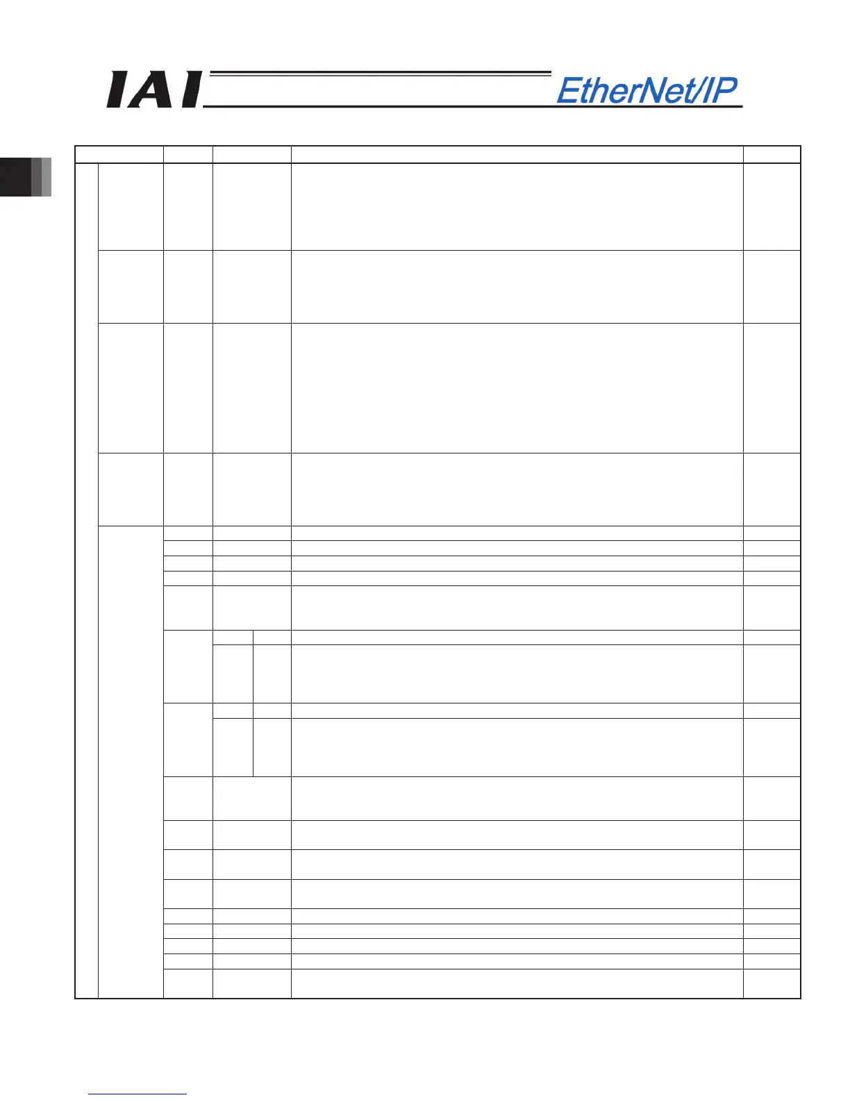
Signal type Bit Symbol Contents Details
Current
position
32-bit
data
-
32-bit signed integer indicating the current position
The setting unit is 0.01mm.
(Example) Reading:000003FF
H
=1023 (decimal)
=10.23mm
* When the value is read in hexadecimal notation, the negative figure is
expressed as a complement of 2.
2.8 (3)
Command
current
32-bit
data
-
32-bit integer
The electrical current presently specified by a command is indicated.
The setting unit is mA.
(Example) Reading:000003FF
H
=1023 (decimal)
=1023mA
2.8 (3)
Current
speed
32-bit
data
-
32-bit signed integer indicating the current position
The current speed is indicated.
Positive value: The actuator is moving in the direction opposite home.
Negative value: The actuator is moving in the direction of home.
The setting unit is 0.01mm/sec.
(Example) Reading:000003FF
H
=1023 (decimal)
=10.23mm/sec
* When the value is read in hexadecimal notation, the negative figure is
expressed as a complement of 2.
2.8 (3)
Alarm
code
16-bit
data
-
16-bit integer
When an alarm is issued, the alarm code is output.
When any alarm is not issued, it is “0”.
Refer to the operation manual for the controller main body for the details of the
alarms.
2.8 (3)
b15 EMGS Emergency stop: An emergency stop is actuated when this signal turns ON. 2.6.7 (2)
b14 PWR Controller ready : This signal turns ON when the controller becomes ready. 2.6.7 (1)
b13 ZONE2 Zone 2:“ON” for the current position within the zone set range 2.6.7 (12)
b12 ZONE1 Zone 1:“ON” for the current position within the zone set range 2.6.7 (12)
b11 PZONE
Position zone:
This signal turns ON when the current position is inside the specified position
zone.
2.6.7 (12)
ACON - Unavailable (ON/OFF is undefined) -
b10
PCON LOAD
Load output judgment:
When this signal is ON, the specified load has been reached. When the signal
is OFF, the load has not been reached yet.
(Refer to operation manual for the controller main body for more information)
2.6.7 (26)
ACON - Unavailable (ON/OFF is undefined) -
b9
PCON TROS
Torque level:
When this signal is ON, the specified load has been reached. When the signal
is OFF, the load has not been reached yet.
(Refer to operation manual for the controller main body for more information)
2.6.7 (27)
b8 RMDS
Operation mode status:
This signal is OFF when the current mode is AUTO, or ON when the current
mode is MANU.
2.6.7 (19)
b7 GHMS
Under Home return Operation: This signal remains ON while home return is in
progress.
2.6.7 (6)
b6 PUSHS
Pressing in progress: This signal remains ON while pressing operation is in
progress.
2.6.7 (25)
b5 PSEL
Pressing and a Miss: This signal turns ON when the actuator missed the work
part in pressing operation.
2.6.7 (23)
b4 SV Operation preparation end: This signal turns ON when the servo turns ON. 2.6.7 (5)
b3 ALM Alarm: This signal turns ON when an alarm occurs. 2.6.7 (3)
b2 MOVE Moving signal: This signal remains ON while the actuator is moving. 2.6.7 (9)
b1 HEND Home return completion: This signal turns ON when home return is completed. 2.6.7 (6)
PLC input
Status
signal
b0 PEND
Positioning completion signal: This signal turns ON when positioning is
completed.
2.6.7 (10)