2. ACON, PCON
56
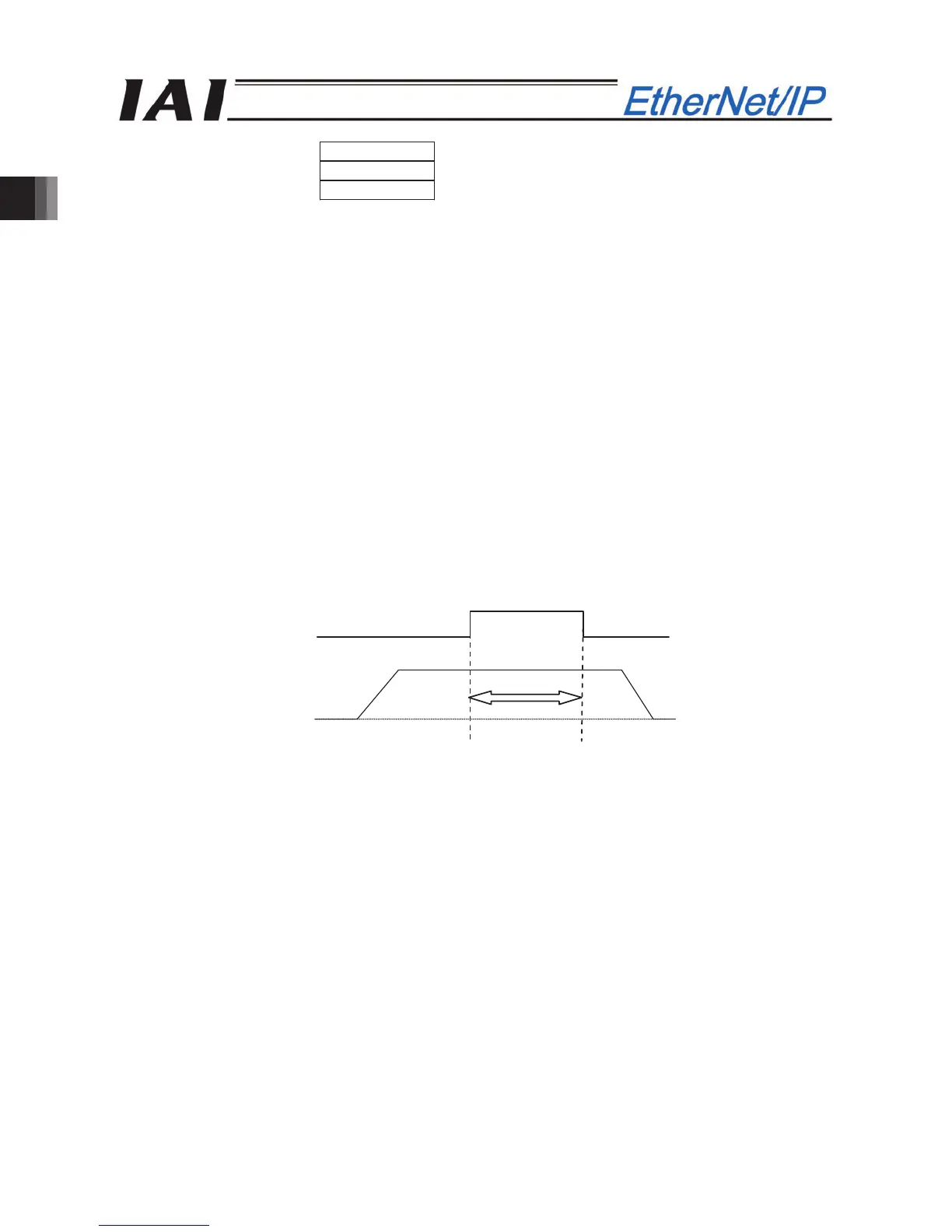
Zone signal
+ direction
Actuator operation
Home
Zone setting -
Zone setting +
(12) Zone 1 (ZONE1) PLC input signal
Zone 2 (ZONE2) PLC input signal
Position zone (PZONE) PLC input signal
These signals are turned ON when the current position of the actuator is within the set domain and turned
OFF when the current position is out of the set domain.
[1] Zone 1, Zone 2
The zone is set using the user parameters.
The Zone 1 Signal is set using the parameter No. 1 “Zone Boundary 1 “+” Side” and No. 2 “Zone Boundary
1 “–“ Side”.
The Zone 2 Signal is set using the parameter No. 23 “Zone Boundary 2 “+” Side” and No. 24 “Zone
Boundary 2 “–“ Side”.
The Zone 1 Signal and Zone 2 Signal become effective when the home return operation is completed. After
that, even during the servo OFF, it is effective.
[2] Position zone
Each zone is set in the position table or using the zone boundary resister.
In the case of the Position/Simplified Direct Value Mode, the PZONE signal is set using the position table.
In the case of the Full direct value mode, the PZONE signal is set using the Zone Boundary Value Register.
(*) In the half direct value mode, there is no PZONE signal.
The PZONE signal becomes effective with the movement command after the home return operation. After
that, even during the servo OFF, it is effective.
 Loading...


