AFE1_AFE2-1:1
I-jet
35
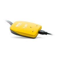
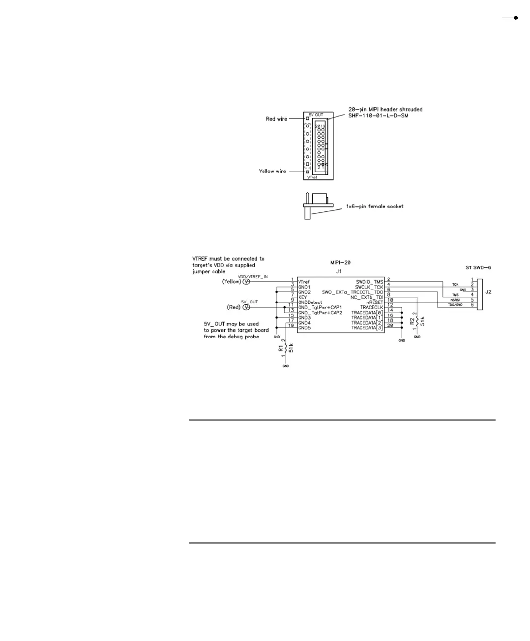
This is a diagram of the ADA-MIPI20-STSWD6 adapter:
These are the pin definitions for the ADA-MIPI20-STSWD6 adapter:
Pin
I-jet
direction
Name Description
1 NC No connection - not used.
2 Output SWCLK
/TCK
SWD clock signal to the target CPU. It is recommended
that this pin is pulled to a defined state of the target
board.
3 GND Common ground.
4I/OSWIO
/TMS
Bi-directional data pin for SWD. This pin should be
pulled up on the target (100k recommended).
5 I/O NSRST System reset is open-drain and active low and should be
pulled-up on the target board. Allows debug probe to
reset the MCU if necessary.
Table 12: ADA-MIPI20-STSWD6 adapter pin definitions