iv
Repair Information........................................................101
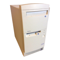
Removals and Replacements for Machine Types 2193, 2194
and 6345........................................................................102
Identifying the Parts of the System Unit.....................103
Top Cover.................................................................105
Adapter Cards...........................................................106
Diskette Drive ...........................................................108
CD-ROM Drive..........................................................110
Hard Disk Drive.........................................................111
System Board ...........................................................112
Power Supply............................................................115
Memory (DIMM)........................................................115
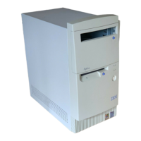
Removals and Replacements for Machine Types 2196, 2197
and 6344........................................................................116
Identifying the Parts of the System Unit.....................117
Top Cover.................................................................119
Adapter Cards ..........................................................120
Diskette Drive ...........................................................121
CD-ROM Drive..........................................................122
Hard Disk Drive.........................................................123
System Board ...........................................................124
Power Supply............................................................127
Memory (DIMM)........................................................127
Parts/Test Point Locations ……………………………….129
Introduction.....................................................................130
Layout of the System Board of Machine Types 2197 and
6344...............................................................................131
Jumper Settings........................................................132
Connectors and Functions ........................................133
Layout of the System Board of Machine Types 2193
and 2196........................................................................134
Jumper Settings........................................................135
Connectors and Functions ........................................136
Power Supply Cable Connector Specifications................137
Main Output Pin Assignment..................................... 138
Factory-Installed Modem Card Layout.............................140
Factory-Installed Modem Card Connector Functions....... 140
3.5-In. Hard Disk Drive Jumper Locations & Settings ......141
CD-ROM Drive................................................................142
Rear Panel Connectors and Features........................143
CD-ROM Drive Jumper Settings......................................143
DIMM Configurations ......................................................144
System Board Connector Pin Signals..............................144
Monitor Port Signals..................................................144
Serial Port Signals ....................................................144
Parallel Port Signals……………………………………. 145
Mouse Port Signals…………………………………….. 145
Keyboard Port Signals ..............................................145
Diskette Drive Cable Connector Signals....................146
IDE Cable Connector Signals....................................147

 Loading...

