132
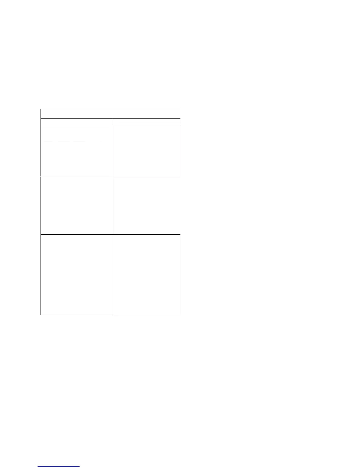
Jumper Settings of the System Board of
Machine Types 2197 and 6344
Table 5-1
Jumper/Settings Function
JP9 JP10 JP11 JP13
2-3 2-3 2-3 2-3
1-2 2-3 2-3 2-3
1-2 2-3 1-2 2-3
1-2 1-2 1-2 2-3
2-3 2-3 2-3 1-2
Bus Frequency(MHz)
CPUCLK SDRAMCLK
66 100
100 100
100 133
133 133
66 66
CPU Core Clock Multiplier
Jumper connected
JP1..........................................
1-2 1-2 1-2
1-2 1-2
1-2 1-2 1-2
1-2
1-2 1-2
CPU Clock Frequency Ratio
5.5
5.0
4.5
4.0
3.5
JP6
CMOS data clear-up
Jumper connected
2-3
1-2
J8
Jumper connected to Front
Panel
1-2
3-4
J9
Jumper connected to power
switch
1-2
Function
Normal
Clear
Indication
Power LED
Hard Disk Drive LED
Power Button
 Loading...


