Figures
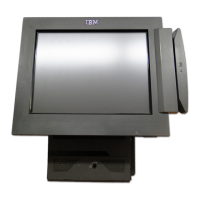
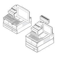
1. Example of the wide and narrow SurePOS 700 series . . . . . . . . . . . . . . . . .1
2. Front panel controls and indicators . . . . . . . . . . . . . . . . . . . . . . . . .3
3. Front panel connectors . . . . . . . . . . . . . . . . . . . . . . . . . . . . .4
4. Overview of rear panel . . . . . . . . . . . . . . . . . . . . . . . . . . . . .4
5. Rear view of input/output available on all models . . . . . . . . . . . . . . . . . . .5
6. USB-only configuration (models 7x1) . . . . . . . . . . . . . . . . . . . . . . . .6
7. USB-only configuration (models 7x2) . . . . . . . . . . . . . . . . . . . . . . . .6
8. RS-485 and USB configuration . . . . . . . . . . . . . . . . . . . . . . . . . .7
9. Location of UPS configuration switches . . . . . . . . . . . . . . . . . . . . . .11
10. UPS rear view . . . . . . . . . . . . . . . . . . . . . . . . . . . . . . . .12
11. Setting the cash drawer using the jumper override . . . . . . . . . . . . . . . . . .18
12. Location of printer jumper on the I/O card . . . . . . . . . . . . . . . . . . . . . .19
13. Example of the powered USB port . . . . . . . . . . . . . . . . . . . . . . . .20
14. Serial number and machine information . . . . . . . . . . . . . . . . . . . . . .23
15. Processor power cable . . . . . . . . . . . . . . . . . . . . . . . . . . . .26
16. Removing the slanted I/O tray . . . . . . . . . . . . . . . . . . . . . . . . . .28
17. Removing the front bezel . . . . . . . . . . . . . . . . . . . . . . . . . . . .29
18. Opening the modesty cover . . . . . . . . . . . . . . . . . . . . . . . . . . .30
19. Replacing the top cover . . . . . . . . . . . . . . . . . . . . . . . . . . . .31
20. Top plate screws . . . . . . . . . . . . . . . . . . . . . . . . . . . . . . .32
21. Opening units with front-service housing . . . . . . . . . . . . . . . . . . . . . .33
22. Removing the CD-ROM . . . . . . . . . . . . . . . . . . . . . . . . . . . .34
23. Example of serial ATA connector (Model C42 only) . . . . . . . . . . . . . . . . . .35
24. Hard disk drive and brackets . . . . . . . . . . . . . . . . . . . . . . . . . .37
25. Master and slave connectors . . . . . . . . . . . . . . . . . . . . . . . . . .37
26. Exhaust fan (Models 742, and 782 only) . . . . . . . . . . . . . . . . . . . . . .38
27. Location of alignment pen holes . . . . . . . . . . . . . . . . . . . . . . . . .39
28. Location of alignment pen holes . . . . . . . . . . . . . . . . . . . . . . . . .40
29. Removing the spline . . . . . . . . . . . . . . . . . . . . . . . . . . . . .41
30. Opened I/O latch . . . . . . . . . . . . . . . . . . . . . . . . . . . . . . .42
31. I/O module holders . . . . . . . . . . . . . . . . . . . . . . . . . . . . . .43
32. Removing the air duct . . . . . . . . . . . . . . . . . . . . . . . . . . . . .44
33. Processor fan and levers . . . . . . . . . . . . . . . . . . . . . . . . . . . .45
34. Heat sink and processor . . . . . . . . . . . . . . . . . . . . . . . . . . . .46
35. Removing the control switch card . . . . . . . . . . . . . . . . . . . . . . . . .47
36. Removing the power supply . . . . . . . . . . . . . . . . . . . . . . . . . . .48
37. Example of Model 742 and 782 processor power cable . . . . . . . . . . . . . . . . .48
38. Removing feature cards . . . . . . . . . . . . . . . . . . . . . . . . . . . .49
39. Serial connectors . . . . . . . . . . . . . . . . . . . . . . . . . . . . . . .50
40. Removing the I/O card cables . . . . . . . . . . . . . . . . . . . . . . . . . .50
41. Power connector . . . . . . . . . . . . . . . . . . . . . . . . . . . . . . .51
42. Dump switch . . . . . . . . . . . . . . . . . . . . . . . . . . . . . . . .52
43. Riser card latch . . . . . . . . . . . . . . . . . . . . . . . . . . . . . . .53
44. Example of stand-offs . . . . . . . . . . . . . . . . . . . . . . . . . . . . .54
45. Planar location . . . . . . . . . . . . . . . . . . . . . . . . . . . . . . .55
46. Power supply housing bracket . . . . . . . . . . . . . . . . . . . . . . . . . .56
47. Lifting the bracket . . . . . . . . . . . . . . . . . . . . . . . . . . . . . .56
48. Removing the UPS . . . . . . . . . . . . . . . . . . . . . . . . . . . . . .57
49. Position of system unit and expansion housing . . . . . . . . . . . . . . . . . . . .58
50. Prying the expansion housing latch upward . . . . . . . . . . . . . . . . . . . . .59
51. Removing the UPS battery . . . . . . . . . . . . . . . . . . . . . . . . . . .60
52. Removing the front USB card . . . . . . . . . . . . . . . . . . . . . . . . . .61
53. Opening the memory module latches . . . . . . . . . . . . . . . . . . . . . . .62
Updated July 14, 2008
© Copyright IBM Corp. 2003, 2008 vii
 Loading...