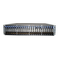
Figure 56. LEDs on the front of a power supply unit
1 Input power
2 DC power
3 Fault indicator
Table 19 on page 67 explains the function and status that is indicated by each of the LEDs. The power
cords for each PSU are accessible from the rear of the expansion enclosure ( 1 ), as shown in Figure 59 on
page 69.
Table 19. Power supply unit LEDs
Function Color Status Description
1 Input power Green On The input voltage is within specication.
Off No power input detected.
2 DC power Green On DC power outputs are within specication.
Off DC power is not available.
3 Fault Amber On A fault is detected in the PSU.
Off No faults are detected.
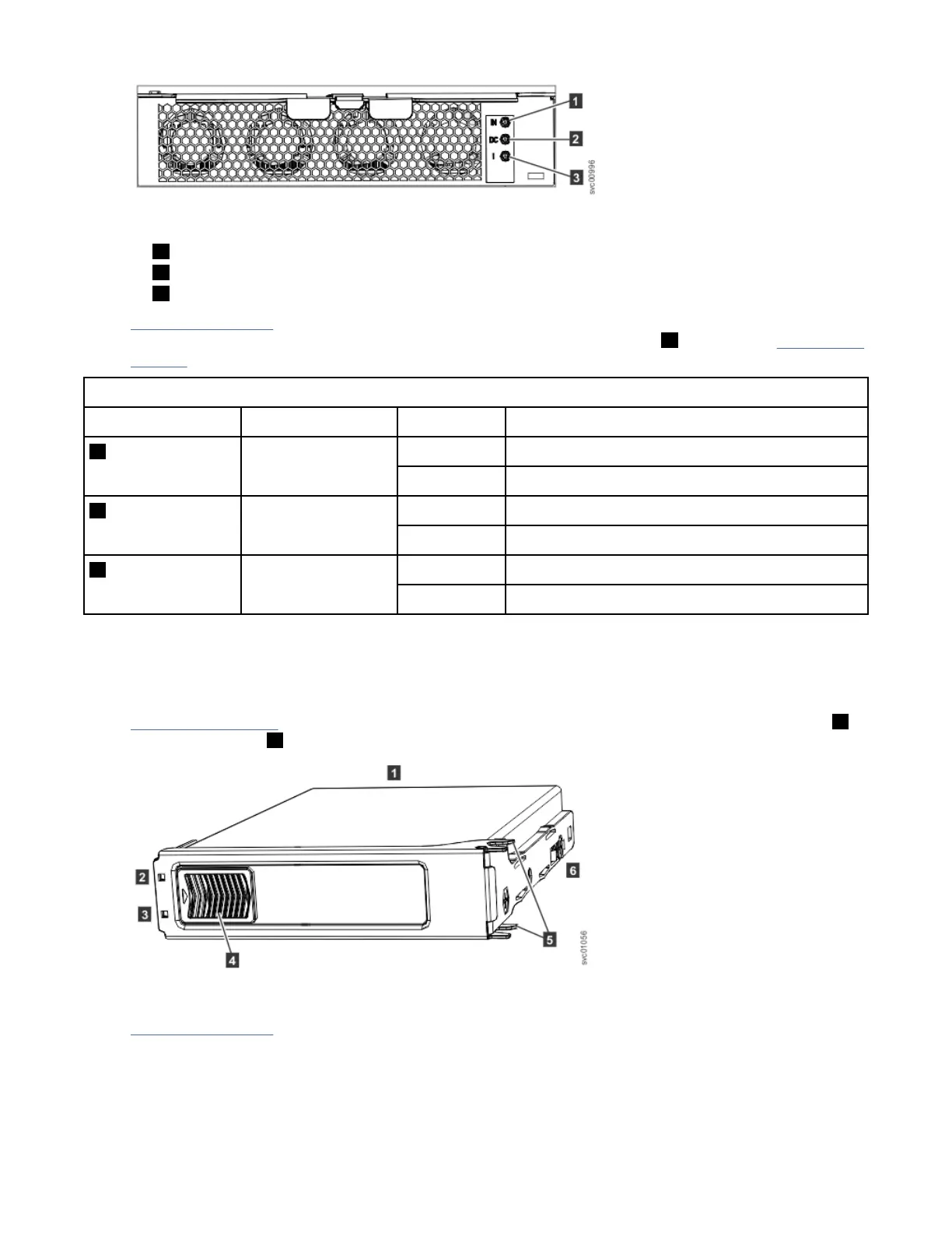
LEDs of drives and secondary expansion modules
Each of the drives and secondary expansion modules within the expansion enclosure has two LED
indicators.
Figure 57 on page 67 shows the components of a drive assembly. Each drive has an online indicator ( 2 )
and fault indicator ( 3 ).
Figure 57. LEDs on a drive assembly
Table 20 on page 68 describes the meaning of the LEDs on each drive.
Chapter 5. Installing Model 092 expansion enclosure
67
 Loading...