Art dw1ks305 goes here.
Table 14. Supported CPU installation combinations
Number of
microprocessors
Microprocessors
socket 1
Microprocessors
socket 2
Microprocessors
socket 3
Microprocessors
socket 4
1 CPU0
1 CPU0
2 CPU0 CPU1
2 CPU0 CPU1
2 CPU0 CPU1
4 CPU0 CPU1 CPU2 CPU3
Notes:
1. CPU0 is the boot strap processor.
2. Combinations highlighted in bold represent the default configurations, which should be
used when processors are installed during manufacturing. The other combinations
shown in the table are supported in the event of an error.
3. If a bad processor in microprocessor socket 1 causes the processor installed in
microprocessor socket 2 to become the boot strap processor and is subsequently
replaced, the processor ordering reverts to the default CPU IDs for the new number of
CPUs, because the FPGA would not hold the last CPU ID assignments and “add in”
the replaced processor.
4. Three-processor configurations are not supported.
5. A microprocessor failure in a four-processor configuration will result in the system
failing down to three functional microprocessor.
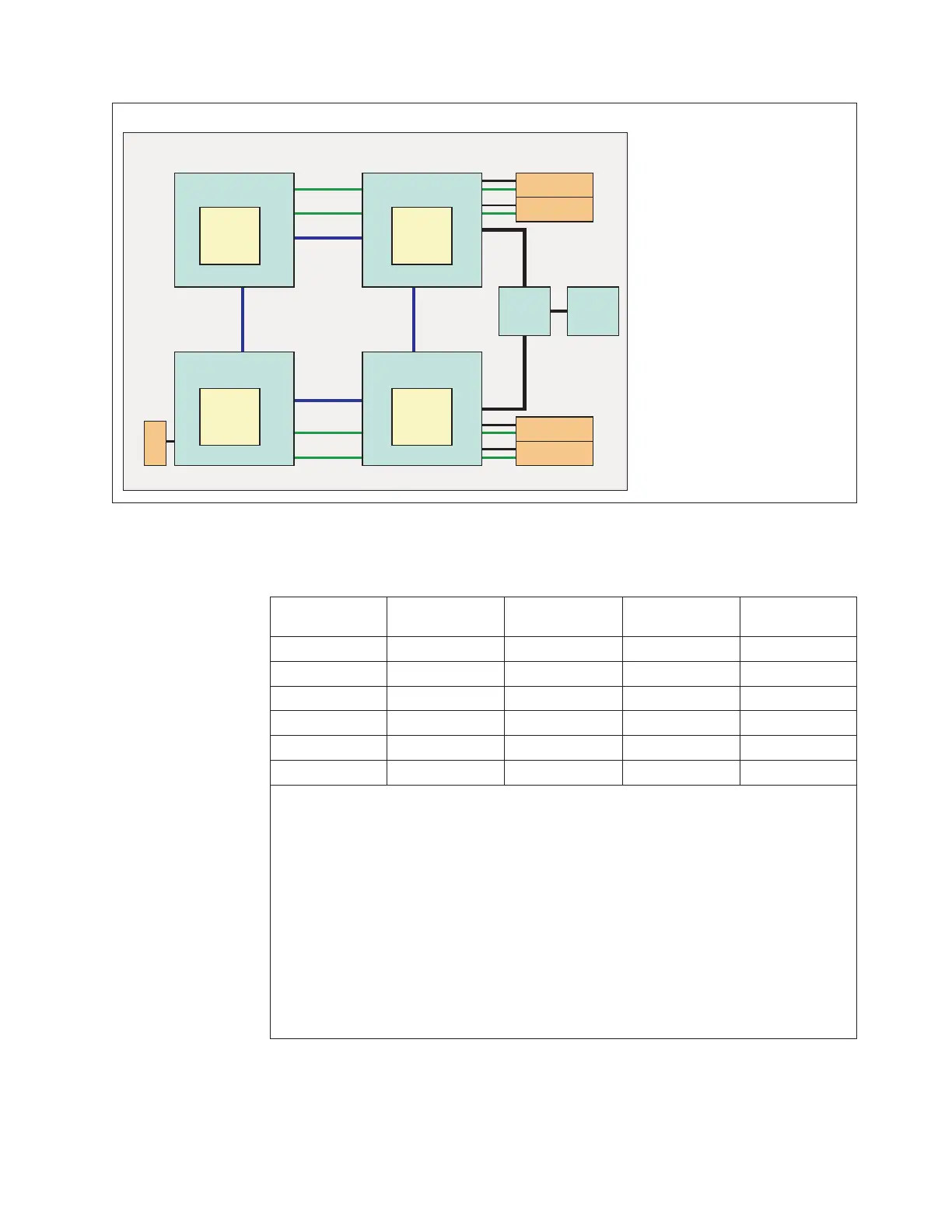
The supported microprocessor configurations are shown in the following
illustrations.
Standard Configuration
Socket 3 Socket 1
Socket 4 Socket 2
CPU
2
CPU
0
CPU
3
CPU
1
ETE
Mezz 1
Mezz 2
Mezz 3
Mezz 4
DMI
SW
PCH
Figure 1. Standard Configuration
Chapter 7. Installing, removing, and replacing compute node components 543