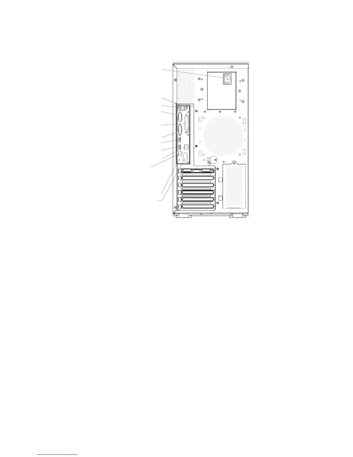
The following illustration shows the connectors on the rear of the non-hot-swap
server models.
Mouse
Keyboard
Serial 1
(COM 1)
Parallel
Power cords
Video
USB 4
(RJ45) Ethernet 10/100/1000
(RJ45) Ethernet 10/100
(for Remote Supervisor Adapter II
SlimLine)
USB 3
NMI button
Serial 2
(COM 2)
Power-cord connector
Connect the power cord to this connector.
AC power LED
This green LED provides status information about the power supply. During
typical operation, both the ac and dc power LEDs are lit. For any other
combination of LEDs, see the Problem Determination and Service Guide on
the IBM System x3400 Documentation CD.
DC power LED
This green LED provides status information about the power supply. During
typical operation, both the ac and dc power LEDs are lit. For any other
combination of LEDs, see the Problem Determination and Service Guide on
the IBM System x3400 Documentation CD.
Mouse connector
Connect a mouse device to this connector.
Keyboard connector
Connect a PS/2 keyboard to this connector.
Serial 1 connector
Connect a 9-pin serial device to this connector.
Parallel connector
Connect a parallel device to this connector.
Video connector
Connect a monitor to this connector.
USB connectors
Connect USB devices to these connectors.
Chapter 3. Server controls, LEDs, and power 41

 Loading...