Installing a memory module
The following notes describe the types of dual inline memory modules (DIMMs) that
the server supports and other information that you must consider when installing
DIMMs:
v The server supports industry-standard, 1.8 V, 240-pin, 667 MHz, PC2-5300
double-data-rate 2 (DDR2), dynamic random-access memory (DRAM) with error
correcting code (ECC) fully buffered dual inline memory modules (DIMMs). These
DIMMs must be compatible with the latest DDR2 667 MHz DRAM fully buffered
DIMM specification. For a list of supported options for the server, see
http://www.ibm.com/servers/eserver/serverproven/compat/us/; then, select your
country and navigate to the list of options for the server.
v The DIMM options that are supported for the server are 512 MB, 1 GB , and 2
GB in x4 or x8 technology, single-rank or double-rank. The server supports a
minimum of 1 GB and a maximum of 32 GB (reduced to 16 GB in mirrored
mode) of system memory. The server comes with two 512 MB DIMMs installed.
v The system board provides eight functional DIMM connectors and supports
two-way memory interleaving when DIMMs are installed in pairs.
Note: DIMM connectors 3, 6, 9, and 12 are not functional. Do not install DIMMs
in these four connectors and do not remove the DIMM thermal baffles
installed in these connectors unless you need to replace the system
board.
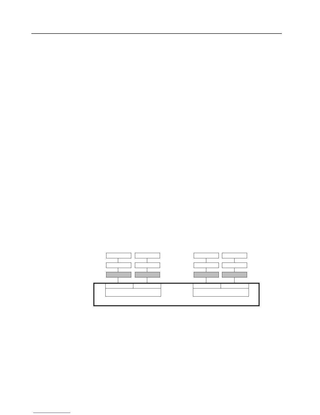
v The memory controller has four fully buffered DIMM channels that are organized
into two branches. Each branch has two channels and each channel controls two
DIMMs. DIMMs that are next to each other (for example, DIMM connector 1 and
DIMM connector 4) within the channels of a branch must be identical in size,
type, speed, and technology. However, the DIMMs in the connector above or
below each other within the channels of a branch do not have to be identical (for
example, the DIMMs in DIMM connector 1 and DIMM connector 2 do not have to
be identical). The following illustration shows how the memory controller is
organized into branches and channels with a pair of DIMMs installed in each
branch.
DIMM 2
DIMM 3
DIMM 1
DIMM 5
DIMM 6
DIMM 4
DIMM 8
DIMM 9
DIMM 7
DIMM 11
DIMM 12
DIMM 10
Memory Controller
Branch 0
Branch 1
Channel 0 Channel 1 Channel 2 Channel 3
v The server can operate in two major modes: mirroring and non-mirroring
(normal). The server can also operate in a single-channel mode when one DIMM
is installed.
v The server supports memory mirroring (mirroring mode) and online-spare
memory.
– Memory mirroring replicates and stores data on DIMMs within two branches
simultaneously. You must enable memory mirroring through the
Configuration/Setup Utility program. To enable memory mirroring in the
Configuration/Setup Utility program, select Devices and I/O Ports →
Advanced Chipset Control → Memory Branch Mode. Use the arrow keys to
change the Memory Branch Mode setting to Mirror; then, save your changes.
16 System x3400 Types 7973, 7974, 7975, and 7976: Installation Guide

 Loading...