XI
QUICK REFERENCE GUIDE
New2001
■ Programming memory channels
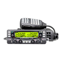
The IC-2720H has a total of 212 memory channels (including
10 scan edges and 2 call channels) for storing often used op-
erating frequency, repeater settings, etc.
Any memory channel can be recalled from either left or right
band.
1. Setting a frequency
In VFO mode, set the desired operating frequency with re-
peater, tone and tuning steps, etc.
➥ Push the desired band’s [V/MHz•SCAN] to select VFO.
➥
Rotate the same band’s [DIAL] to set the desired frequency.
• Set other data, such as repeater tone, duplex information, tuning
step), if desired.
2. Selecting a memory channel
Push the same band’s [M/CALL•MW] for 1 sec., then rotate
the [DIAL] to select the desired memory channel.
•“!” indicator and memory channel number blink.
3. Writing a memory channel
Push and hold the [M/CALL•MW] for 1 sec. to program.
• 3 beeps sound
• Return to VFO mode automatically after the program.
• Memory channel number automatically increases when continuing
to push the [M/CALL•MW] after programming.
MAIN
T X
M
Push [M/CALL•MW] for 1 sec.
IC-2720H_2.qxd 03.5.13 9:45 Page XI (1,1)
 Loading...