17
3
INSTALLATION AND CONNECTIONS
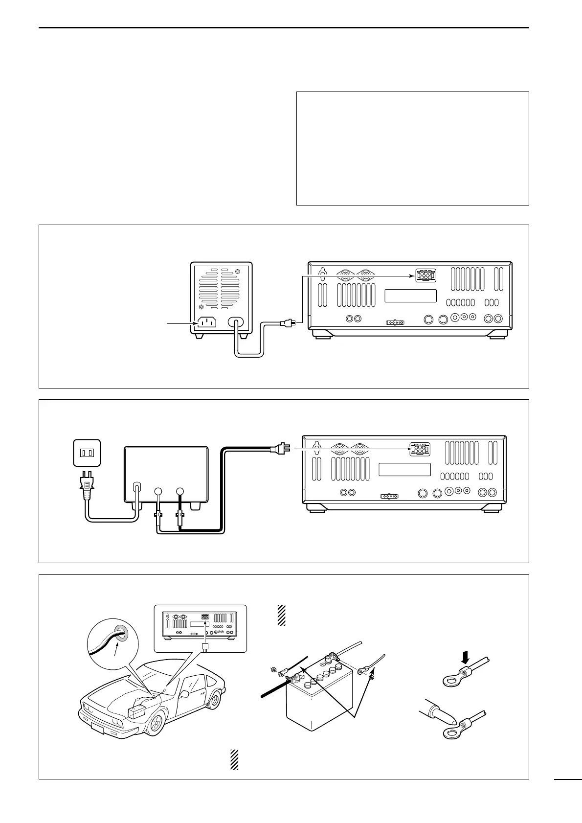
■ Power supply connections
Use the optional PS-125 DC power supply with a 25 A
capacity when operating the transceiver with AC
power. Refer to the diagrams below.
CAUTION: Before connecting the DC power
cable, check the following important items. Make
sure:
•The [POWER] switch is OFF.
•Output voltage of the power source is 12–15 V
when you use a non-Icom power supply.
•DC power cable polarity is correct.
Red : positive + terminal
Black : negative _ terminal
CONNECTING A DC POWER SUPPLY
NEVER connect to
a 24 V battery.
NOTE: Use terminals for
the cable connections.
NEVER connect to a battery without supplied DC fuses,
otherwise a fire hazard may occur.
CONNECTING PS-125 DC POWER SUPPLY