10
74
OPTION INSTALLATION
Follow the case and cover opening procedures shown
here when you want to install an optional unit or adjust
the internal units, etc.
CAUTION: DISCONNECT the DC power cable
from the transceiver before performing any work on
the transceiver. Otherwise, there is danger of elec-
tric shock and/or equipment damage.
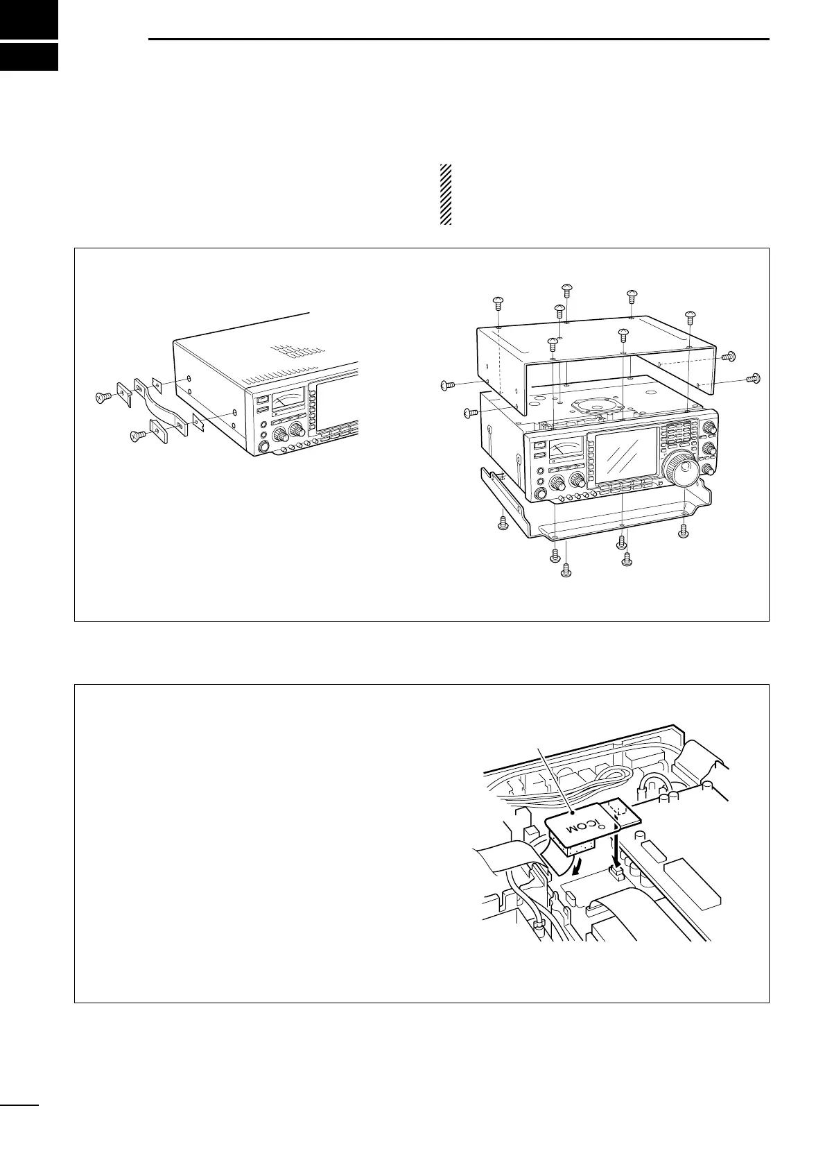
■ Opening the transceiver’s case
The UT-102 announces the accessed readout’s fre-
quency, mode, etc. (S-meter level can also be an-
nounced—p. 71) in a clear, electronically-generated
voice, in English (or Japanese).
➥ Push [LOCK/SPEECH] for 1 sec. to announce the
frequency, etc.
q Remove the top and bottom covers as shown
above.
w Remove the protective paper attached to the bot-
tom of the UT-102 to expose the adhesive strip.
e Plug UT-102 into J3502 on the MAIN unit as
shown in the diagram at right.
r Adjust the trimmer SPCH to set the speech level if
desired. Refer to inside views on p. 78.
t Return the top and bottom covers to their original
positions.
■ UT-102
VOICE SYNTHESIZER UNIT
q Remove 2 screws from the left side of the trans-
ceiver to remove the carrying handle as shown
below.
w Remove 7 screws from the top of the transceiver
and 4 screws from the sides, then lift up the top
cover.
e Turn the transceiver upside down.
r Remove 6 screws from the bottom of the trans-
ceiver, then lift up the bottom cover.