UR-FR5100/UR-FR6100 Installation
16
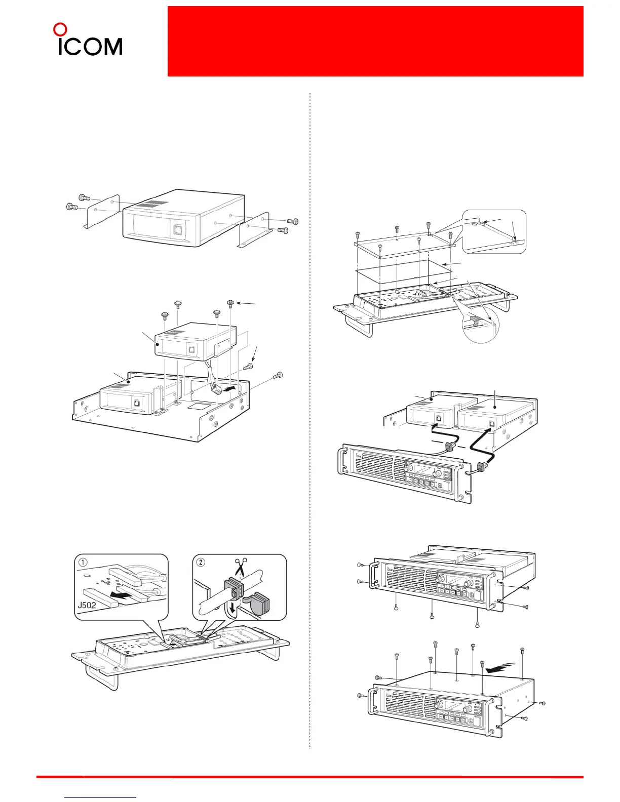
INSTALLATION
• Install the UR-FR5100 or UR-FR6100(channel
extension module)
1. Attach the supplied angles to both sides of the
channel extension module, and tighten the 2
supplied screws (M4×8) on each side.
2. Install the channel extension module using the
supplied screws (Tapping screws: M3×8, Set screws:
M3×6) as shown below.
• Connect the control cable
1.Connect the supplied control cable to J502 on the
front board as shown below.
2. Cut the rubber caps of the control cables, then
insert the rubber caps to the front panel’s chassis as
shown below.
Set screws
Tapping
screws
Channel extension
module
Channel module
(original)
ASSEMBLE THE UNIT
1. Replace the rubber seal and shielding plate of the
front panel, then tighten the 6 screws.
• Make sure the rubber seal is properly seated in the
groove of the chassis.
• Be sure to match the correct positions of the holes of
the shielding plate and projections of the front panel’s
chassis.
2. Connect the control cables to the channel
modules.
3. Return the front panel, top cover and screws to
their original positions.
Channel extension module
Channel module
(original)
Shorter cable
(lower side)
Longer cable
(upper side)
Projections
Rubber seal
Holes

 Loading...


