3-1-2 UR-FR5100/UR-FR6100 Installation
15
UR-FR5100/UR-FR6100 CHANNEL
EXTENSION MODULES
SUPPLIED ACCESSORIES
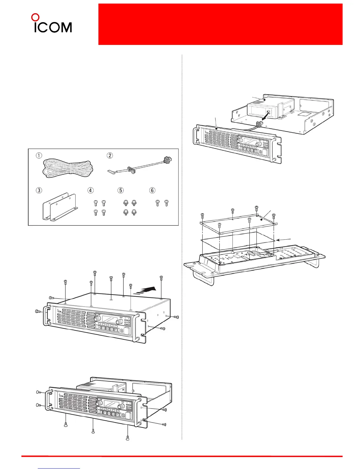
1. DC power cable :1
2.Control cable :1
3. Angles :2
4. Screws (M4×8 mm) :4
5.Set screws (M3×6 mm) :4
6.Tapping screws (M3×8 mm) :2
1 mm = 1/32 inch
OPENING CASE
1. Remove 7 screws from top and 2 screws each from
both sides of the repeater, then slide off the top cover
to the direction of the arrow as illustrated below.
2.Remove 3 screws from bottom and 2 screws each
from both sides of the repeater.
3. Disconnect the control cable from the channel
module (original), then remove the front panel.
4. Remove 6 screws from the front panel, then
remove the shielding plate and rubber seal.
Channel module(original)
Front panel
Shielding plate
Rubber seal

 Loading...


