5-2 Digital-analogue Cross System
38
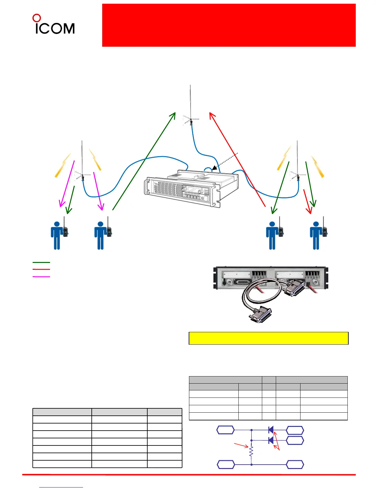
Connection example
This is an example of Digital and analogue cross
mode operation. The IDAS radio (including repeater)
can receive both analogue mode and digital mode
signals on a single channel. This function is useful
when introducing digital system components into an
existing analogue system. It allows the system
operator to communicate with analogue only
terminals while utilizing the digital features as
required.
Descriptions Model Number Quantity
UHF Repeater IC-FR6100
UHF RF Module UR-FR6100
TX Antenna
RX Antenna
Multi Coupler
Interface Cable 25p to 25p
Connect two repeaters by interface cable (25p to 25p).
These interface cables are not sold as Icom accessories,
therefore please assemble the interface cable by
yourself. The connection diagram is as follows;
Digital - analogue / analogue - analogue Cross
mode connection
•analogue TX signal can be RX by analogue/Digital
radios
•Digital TX signal can be RX by analogue/Digital
radios
•Repeater/Digital radio operate in Mixed-Digital mode
•analogue radio operates in analogue mode
•analogue repeater for analogue TX only
analogue modulated signal from analogue area
Digital modulated signal from digital area
analogue modulated signal from digital area
Frequency
f
1
: Up link (both Digital & analogue)
f
2
: analogue Down link
f
3
: Digital or analogue Down link
analogue Repeater (25pin) Digital Repeater (25pin)
Pin Description Pin No. Pin No. Pin Description
MODIN 8
22 AFOUT
EPTT 19
21 Digital Audible
EPTT 19
23 analogue Audible
GND 7,14
7,14 GND
System requirement (One site)
P21
P23
P19
Digital Audible
analogue
Audible
EPTT
Switching Diode e.g.
MA2C167
Resistor 47kΩ
P7,1
4
GND
P7,1
4
GND
Linking
interface
(25pin)
analogue H/H Digital H/H
Tx =
f
2
CTCS
S
Tx = f
1
Rx = f
2
CTCSS
Tx = f
1
Rx = f
3
Tx = f
3
IC-FR6100 + UR-FR6100
RX Antenna
TX Antenna 1
TX Antenna 2
Rx = f
1

 Loading...


