43
4
PANEL DESCRIPTION
4
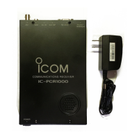
qANTENNA CONNECTOR1 [ANT1]
Connects a 50 Ω antenna with a BNC connector and a 50
Ω coaxial cable.
wDATA JACK [DATA]
Connect to a PC via the RS-232 cable (D-sub 9 pin) for data
communication in the RS-232 format.
ePACKET JACKS [PACKET1/2]
Connect a TNC (Terminal Node Controller), etc. for data
communications. The receiver can receive 9600 bps
packet communication (AFSK).
rUSB CONNECTOR [USB]
Connects to a PC via the supplied USB cable.
tANTENNA CONNECTOR2 [ANT2]
Connects a 50 Ω antenna with a BNC connector and a 50
Ω coaxial cable.
yEXTERNAL SPEAKER JACK [EXT SP]
Connects an 8 Ω external speaker.
• Audio output power is more than 0.5 W.
uCONTROLLER [CONTROLLER]
Connects to a controller via an extension cable. This con-
nector is only used for IC-R1500 or R2500’s controller op-
eration.
• No connection is necessary when the control software is in use.
CAUTION: NEVER insert any other than specified con-
trol cable such as metallic object, otherwise Main unit
may be damaged.
iPOWER JACK [DC IN]
Accepts 12 V DC ±15% with the supplied DC power cable.
oGROUND TERMINAL [GND]
Connect this terminal to a ground.

 Loading...