3
1 PANEL DESCRIPTION
New2001
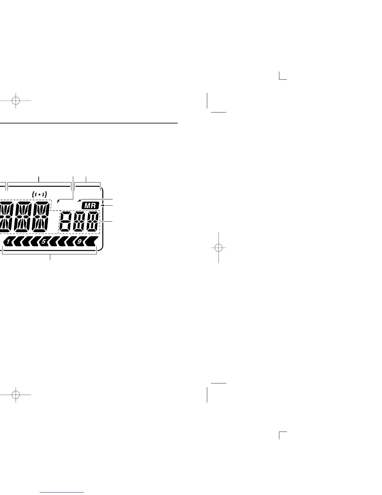
■ Function display
qFREQUENCY READOUT
Shows variety of information, such as an operating fre-
quency, set mode contents, memory names.
• The smaller “75,” “50” and “25” to the right of the readout indi-
cate 0.75, 0.5 and 0.25 kHz, respectively.
• The decimal point blinks during scan.
wLOCK INDICATOR (p. 10)
Appears when the lock function is activated.
eRECEIVE MODE INDICATOR (p. 12)
Shows the selected receive mode.
• FM, WFM and AM are available.
rDUPLEX INDICATORS (p. 14)
“DUP” appears when plus duplex, “–DUP” appears when
minus semi-duplex (repeater) operation is selected.
tTONE INDICATORS
➥ “T SQL” appears while the tone squelch function is in
use. (p. 35)
➥ “DTCS” appears while the DTCS squelch function is in
use. (p. 35)
➥ “S” appears with the “T SQL” or “DTCS” indicator
while the pocket beep function
(with CTCSS or DTCS) is in
use. (p. 35)

 Loading...


