_ Installation Instructions
Blockoff Plate Removed
FIGURE 7 (Return Air Compartment)
Condensate Drain
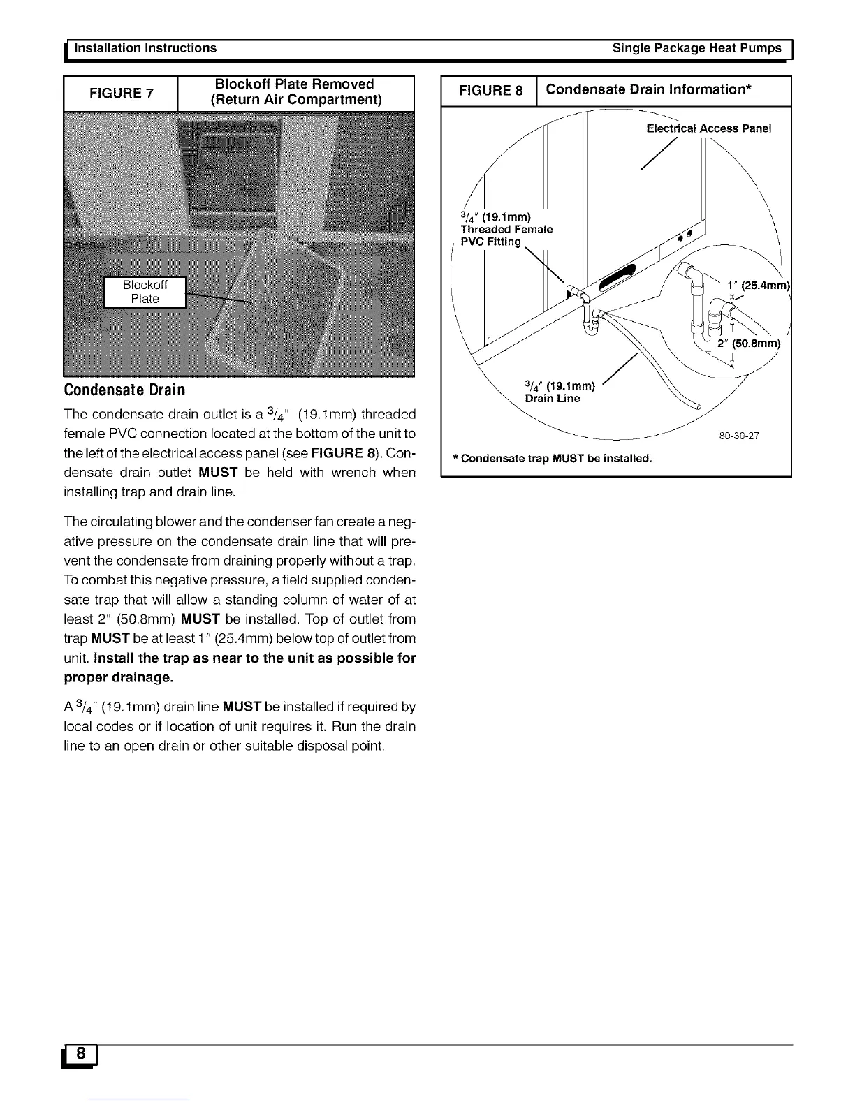
The condensate drain outlet is a 3/4" (19.1mm) threaded
female PVC connection located at the bottom of the unit to
the left of the electrical access panel (see FIGURE 8). Con-
densate drain outlet MUST be held with wrench when
installing trap and drain line.
The circulating blower and the condenser fan create a neg-
ative pressure on the condensate drain line that will pre-
vent the condensate from draining properly without a trap.
To combat this negative pressure, a field supplied conden-
sate trap that will allow a standing column of water of at
least 2" (50.8mm) MUST be installed. Top of outlet from
trap MUST be at least 1" (25.4mm) below top of outlet from
unit. Install the trap as near to the unit as possible for
proper drainage.
A3/4" (19.1mm) drain line MUST be installed if required by
local codes or if location of unit requires it. Run the drain
line to an open drain or other suitable disposal point.
Single Package Heat Pumps I
FIGURE 8
3/4" (19.1mm)
Threaded Female
PVC Fitting
I Condensate Drain Information*
Electrical Access Panel
1" (25.4mm)
3/4" (19.1mm)
Drain Line
2" (50.8mm)
* Condensate trap MUST be installed.
80-30-27
 Loading...