_ Installation Instructions Single Package Heat Pumps I
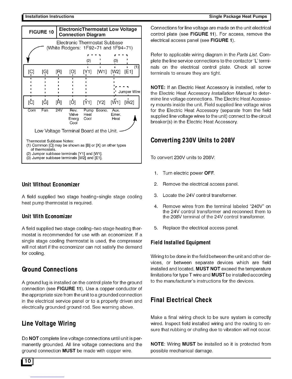
ElectronicThermostat Low VoltageFIGURE 10 Connection Diagram
Electronic Thermostat Subbase
y (White Rodgers: 1F92-71 and 1F94-71)
f " " _ 6"'''1
(2) ' (3) '
v I T !
.... (t)I[C] [G] [R] [O1 [YI] [Wl] [W21 [Ell
I
l
I
!
,' Jumper Wire
i
I I I I I I I
[C] [G] [R] [O1 [YI] [Y21 [Wl] ['v_/21
Corn Fan 24V
Rev. Pump Econo. Aux.
Valve Heat Emer.
Energ Coo! Heat
Cool
Low Voltage Terminal Board at the Unit.
Thermostat Subbase Notes:
(1) Common [C] may be shown as [B] or IX] on other types
of thermostats.
(2) Jumper subbase terminals [Y1] and [Wt].
(3) Jumper subbase terminals [W2] and [Et].
Connections for line voltage are made on the unit electrical
control plate (see FIGURE 11). For access, remove the
electrical access panel (see FIGURE 1).
Refer to applicable wiring diagram in the Parts List. Com-
plete the line service connections to the contactor 'L' termi-
nals on the electrical control plate. Check all screw
terminals to ensure they are tight.
NOTE: If an Electric Heat Accessory is installed, refer to
the Electric Heat Accessory Installation Manual to deter-
mine line voltage connections. The Electric Heat Accesso-
ry mounts inside the unit. Field supplied line voltage wires
for the Electric Heat Accessory (separate from the field
supplied line voltage wires to the unit) connect to the circuit
breaker(s) in the Electric Heat Accessory.
Converting 230V Units to 208V
To convert 230V units to 208V:
1. Turn electric power OFF.
Unit Without Economizer 2. Remove the electrical access panel.
A field supplied two stage heating-single stage cooling
heat pump thermostat is required.
Unit With Economizer
3. Locate the 24V control transformer.
4. Remove wires from the terminal labeled "240V" on
the 24V control transformer and reconnect them to
the 208V terminal of the 24V control transformer.
A field supplied two stage cooling-two stage heating ther-
mostat is recommended for use with an economizer. If a
single stage cooling thermostat is used, the compressor
will not start if the economizer can not satisfy the demand
for cooling.
GroundConnections
A ground lug is installed on the control plate for the ground
connection (see FIGURE tt). Use a copper conductor of
the appropriate size from the unit to a grounded connection
in the electrical service panel or to a properly driven and
electrically grounded ground rod. See warning above.
5. Replace the electrical access panel.
Field Installed Equipment
Wiring to be done in the field between the unit and other de-
vices, or between separate devices which are field
installed and located, MUST NOT exceed the temperature
limitations for type T wire and MUST be installed according
to the manufacturer's instructions for the devices.
Final Electrical Check
Une Voltage Wiring
Do NOT complete line voltage connections until unit is per-
manently grounded. All line voltage connections and the
ground connection MUST be made with copper wire.
Make a final wiring check to be sure system is correctly
wired. Inspect field installed wiring and the routing to en-
sure that rubbing or chafing due to vibration will not occur.
NOTE: Wiring MUST be installed so it is protected from
possible mechanical damage.
 Loading...