I Single Package Heat Pumps Installation Instructions
5. ElectricalWiring
Electrical shock hazard.
Disconnect power at fuse box or service panel
before making any electrical connections.
Unit MUST be grounded to electrical service pan-
el.
Failure to follow this warning can result in prop-
erty damage, personal injury, and/or death.
NOTE: All electrical work MUST conform with the require-
ments of local codes and ordinances and in the United
States with National Electrical Code ANSI/NFPA 70-1990
(or current edition) and in Canada with CSA C22.1 - Cana-
dian Electrical Code Part 1 (or current edition). Provide line
voltage power supply from a separate fused circuit with a
disconnect switch (when required) located within sight of
the unit. Supply voltage, amperage, wire, fuse and discon-
nect switch sizes MUST conform with specifications in the
Parts List and on the unit rating plate.
Wiring MUST be protected from possible mechanical dam-
age and MUST NOT interfere with removal of access pan-
els, filters, etc.
All exposed wiring and connections MUST be made with
weatherproof cable or wire unless installed in conduit.
LowVoltage Wiring
Low voltage connections are made on the low voltage ter-
minal board inside the electrical control compartment (see
FIGURE 11). For access, remove the electrical control ac-
cess panel (see FIGURE 1).
Refer to the Parts List for the connection wiring diagram for
the applicable model and to the instructions included with
the thermostat.
Route low voltage wires through the port located at the bot-
tom left corner of the blower access panel side of the unit.
Route low voltage wires behind unit cornerpost, through
the wire clip provided, and up to the low voltage terminal
board.
NOTE: If an Electric Heat Accessory is installed, see the
Electric Heat Accessory Installation Manual for low voltage
connections. If an economizer is installed, see the follow-
ing section, Low Voltage Wiring With Economizer Option.
LowVoltage Wiring With Economizer Option
Same as the above Low Voltage Wiring section except re-
fer to the connection wiring diagram supplied with the
economizer.
NOTE: The jumper wire on the heat/cool relay must be
disconnected from terminal number 3 and recon-
nected to the economizer wire terminated with an in-
sulated male quick connect. See the
installation/operation manual accompanying the
economizer for more information.
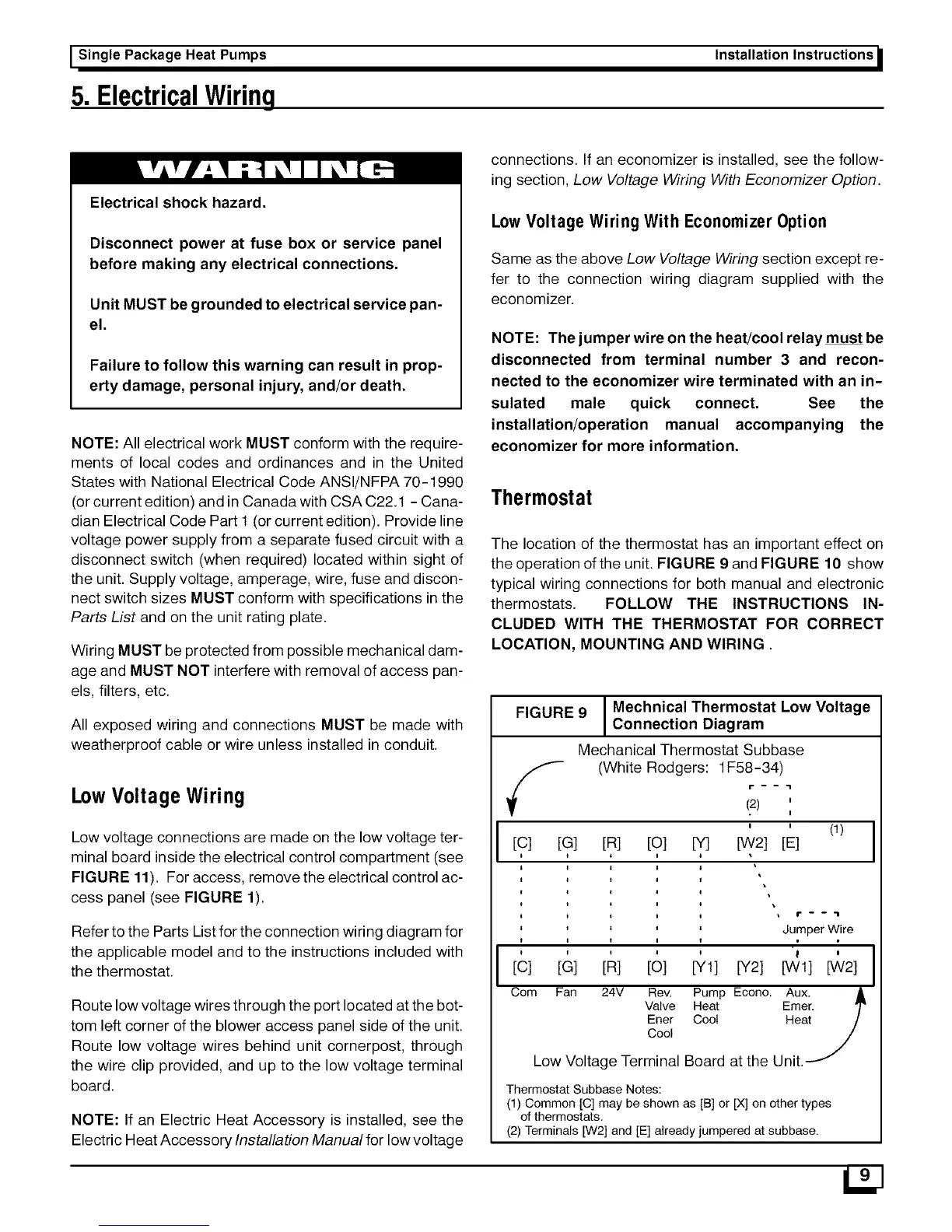
Thermostat
The location of the thermostat has an important effect on
the operation of the unit. FIGURE 9 and FIGURE t 0 show
typical wiring connections for both manual and electronic
thermostats. FOLLOW THE INSTRUCTIONS IN-
CLUDED WITH THE THERMOSTAT FOR CORRECT
LOCATION, MOUNTING AND WIRING
FIGURE 9
[c]
JMechnical Thermostat Low Voltage
Connection Diagram
Mechanical Thermostat Subbase
(White Rodgers: 1F58-34)
(2) '
I
' ' (1)
[G] [R] [O] [Y] [W2] [E]
[c]
Com
[G] [R] [O] [Y1] [Y2]
Fan 24V Rev, Pump Econo.
Valve Heat
Ener Cool
Cool
Jumper Wire
[Wl] [W2]
Aux.
Emer.
Heat
Low Voltage Terminal Board at the Unit.
Thermostat Subbase Notes:
(1) Common [q may be shown as [B] or [X] on other types
of thermostats.
(2) Terminals [W2] and [E] already jumpered at subbase.
 Loading...