Rated output Minimum bore Nominal Size (DN)
kW mm in
301 to 600 50 2
601 and above
* *
'Steel pipe sizes complying with medium or heavy quality or BS
1387.
Detail reference should be made to the appropriate standards listed on page 4.
The information and guidance given below is not intended to override any
requirements of the above publications or the requirements of the local authority,
gas or water undertakings.
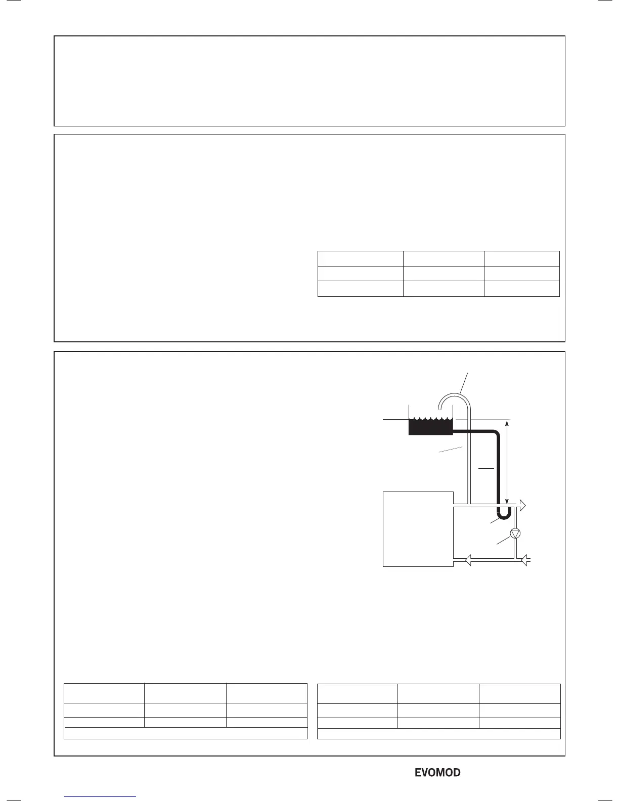
The vertical distance between the pump and feed/expansion cistern MUST
comply with the pump manufacturer's minimum requirements, to avoid cavitation.
Should these conditions not apply either lower the pump position or raise the
cistern above the minimum requirement specied by Ideal Boilers. The
isolation valves should be tted as close to the pump as possible.
The information provided is based on the following assumptions:
1. An independent open vent/safety pipe connection is made immediately after
the system ow pipe connection.
2. An independent cold feed/expansion pipe connection is made immediately
after the open vent/safety pipe connection.
3. The maximum ow rate through the boiler is based on a temperature
difference of 20
o
C at full boiler output.
4. The boiler is at the highest point of circulation in the system. Systems
designed to rise above the boiler ow tappings will automatically require a
minimum static head higher than that shown.
5. The position of the open vent/safety pipe above the expansion cistern
water level is given as a guide only. The nal position will depend upon
the particular characteristics of the system. Pumping over of water into the
expansion cistern must be avoided.
6. Both open vent/safety pipe and cold feed/expansion pipes must be of
adequate diameter to suit the output of the boiler. Refer to Tables below and
BS 6644:2005.
10
OPEN VENTED SYSTEM REQUIREMENTS
Note.
This diagram does not show safety valves, water
ow switches, etc. necessary for the safe operation
of the system.
Open Vent Pipe Sizes
Rated output Minimum bore Nominal Size (DN)
kW mm in
301 to 600 38 1
1
/
2
601 and above 50 2
Steel pipe sizes complying with medium or heavy quality or BS 1387.
Cold Feed Pipe Sizes
Note. Refer to Frame 29 for typical system arrangements.
* Determine using A=3.5 x QR (QR = heat output (Kw) A = area (mm
2
)
9
VENTILATION
The ventilation requirements of these boilers are dependant
on the type of ue system used, and their heat input. All vents
must be permanent with no means of closing, and positioned to
avoid accidental obstructions by blocking or ooding.
Detail reference should be made to BS. 6644 for inputs between
70kW and 1.8MW (net).
In IE refer to the current edition of I.S.820:2000. The following
notes are for general guidance only:
Dust contamination in the combustion air may cause blockage
of the burner slots. Unless the boiler room provides a dust free
environment then direct connection of the air intake via ducting
to clean outside air should be used.
IMPORTANT NOTE: If combustion air is drawn from within
the boiler room, ensure no dust or airborne debris can be
ingested into the appliance. Dusty concrete ooring should
be sealed to reduce the presence of dust.
The temperature within a boiler room shall not exceed 25
o
C
within 100 mm of the oor, 32
o
C at mid height and 40
o
C within
100 mm of the ceiling.
Open Flued Installations
If ventilation is to be provided by means of permanent high and
low vents communicating direct with outside air, then reference
can be made to the sizes below. For other ventilation options
refer to BS. 6644. In IE refer to the current edition of I.S.820.
Required area (cm
2
) per kW of total rated input (net)
Boiler Room Enclosure
Low level (inlet) 4 10
High level (outlet) 2 5
Note: Where a boiler installation is to operate in summer months
(e.g. DHW) additional ventilation requirements are stated, if
operating for more than 50% of time (refer to BS6644).
8
BOILER CLEARANCES
The minimum dimensions as indicated must be respected to
ensure good access around the boiler.
Recommended minimum clearances are as follows.
Rear: 750mm or adequate space from the rear of the jacket to make the
ue connections, drain connection, ue and any safety or control devices.
Left Side: 400mm Right Side: 450mm
Front: 600mm for normal service and replacement of
components. However, it is noted that 1.2m is required in the
event of heat exchanger replacement.
Top: 300mm (clearance above boiler casing).
14
- Installation & Servicing

 Loading...


