11
SEALED SYSTEM REQUIREMENTS
Working pressure 6 bar maximum.
Particular reference should be made to BS. 6644 and Guidance
note PM5 "Automatically controlled steam and hot water boilers"
published by the Health and Safety Executive.
The information and guidance given below is not intended to
override any requirements of either of the above publications or
the requirements of the local authority, gas or water undertakings
.
In general commercial closed pressurised systems are provided
with either manual or automatic water make up.
In both instances it will be necessary to t automatic controls
intended to protect the boiler, circulating system and ancillary
equipment by shutting down the boiler plant if a potentially
hazardous situation should arise.
Examples of such situations are low water level and operating pressure
or excessive pressure within the system. Depending on circumstances,
controls will need to be either manual or automatic reset. In the event
of a shutdown both visual and audible alarms may be necessary.
Expansion vessels used must comply with EN 13831 and must be sized
on the basis of the total system volume and initial charge pressure.
Initial minimum charge pressure should not be less than
1.0 bar (14.7psi) and must take account of the static head and
specication of the pressurising equipment. The maximum
water temperatures permissible at the point of minimum
pressure in the system are specied in Guidance Note PM5.
When make up water is not provided automatically it will be
necessary to t controls which shut down the plant in the event
of the maximum system pressure approaching to within 0.35bar
(5psi) of the safety valve setting.
Other British Standards applicable to commercial sealed
systems are:
BS. 6880: Part 2 BS. 1212 BS. 6281: Part 1
BS. 6282: Part 1 BS. 6283: Part 4
12
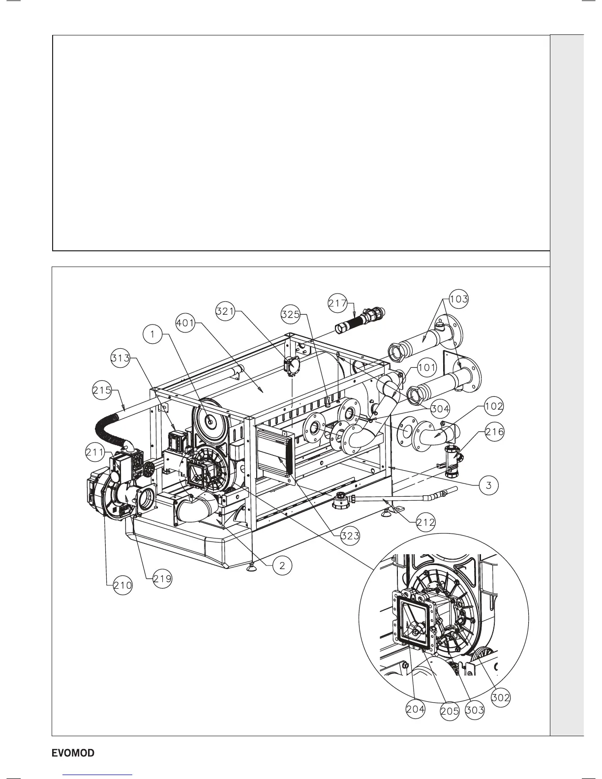
BOILER ASSEMBLY
Legend
INSTALLATION
1. Flue Sampling Point
2. Mains Connection Box
3. Earth Bonding Point
101. Flow pipe
102. Return Pipe
103. Hose Flexible 2
1
/2"
204. Flap Flange Unit
205. Flange Gasket
210. Fan
211. Gas Valve
212. Condensate Assy.
215. Gas Pipe
216. Condensate Trap
217. Gas Pipe Flexible 1
1
/4"
219. Venturi
302. Ignition Electrode
303. Detection Electrode
304. Thermistor (Flow)
304. Thermistor (Return)
313. Module PCB
321. Condensate Blockage
Pressure Switch
323. Master PCB box
325. Water Pressure Switch
401. Heat Exchanger
15
- Installation & Servicing

 Loading...


