26
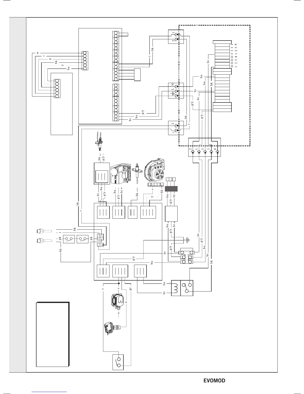
PICTORIAL WIRING DIAGRAM
Note: this diagram is for the Master Module
The slave modules have the same wiring except that there is no Master PCB, CUI PCB or
Installer Wiring Box
The connection position for the Module Pumps in the Mains Wiring Box is shown by the
numbers in the Mains Wiring Box
(I1 = Module Pump 1 Live In, I2 = Module Pump 2 Live In, etc
O1 = Module Pump 1 Live Out, O2 = Module Pump 2 Live Out etc.
Master PCB
Installer Wiring Box
Spark
Electrode
Flame
Sense
Electrode
Gas
Valve
Spark
Generator
Module
Pump
Relay
Module
PCB
Diagnostic
Connection
Condenstate
Protection Switch
Water
Pressure
Switch
CUI PCB
eBus
Plug/
Socket
IEC
Plug/
Socket
eBus
Plug/
Socket
Module Mains
Plug Socket
Electrical
Filter
Fan
Ferrite

 Loading...


