FOUNDATION / LOCATION OF BOILER
The boiler must stand on a oor which must be at, level and of a
suitable load bearing capacity to support the weight of the boiler
(when lled with water) and any ancillary equipment.
Ideally the boiler should be placed on a plinth exceeding the plan
area of the boiler by 75mm on each side and at least 100mm
high.
The boiler must not be tted outside.
GAS SUPPLY
The local gas supplier should be consulted, at the installation
planning stage, in order to establish the availability of an adequate
supply of gas. An existing service pipe must NOT be used without
prior consultation with the local gas supplier.
A gas meter can only be connected by the local gas supplier or by
a Gas Safe Registered Engineer or in IE by a competent person.
An existing meter should be checked, preferably by the gas
supplier, to ensure that the meter is adequate to deal with the
dynamic rate of gas supply required. A minimum working gas
pressure of 17mbar MUST be available at the boiler inlet for
Natural gas.
Do not use pipes of smaller size than the boiler inlet gas
connection.
The complete installation MUST be tested for gas soundness and
purged in accordance with the appropriate standards.
Gas Boosters
A gas booster is required if the gas pressure available at the boiler
is lower than that required by the boiler manufacturer to attain the
ow rate for maximum burner input rating.
Location of the booster requires careful consideration but
should preferably be closer to the burner rather than the gas
meter. Ventilation should also be considered to ensure ambient
temperature do not exceed designed recommendations. Further
guidance is provided in IGE/UP/2.
FLUE INSTALLATION
The ue header for 500-1000 boilers is supplied.
IMPORTANT. It is the responsibility of the installer to ensure,
in practice, that products of combustion discharging from the
terminal cannot re-enter the building or any other adjacent
building through ventilators, windows, doors, other sources of
natural air inltration, or forced ventilation / air conditioning.
If this should occur the appliance MUST be isolated from the
gas supply and labelled as 'unsafe' until corrective action can be
taken.
Terminal Position
Due to the high efciency of the boilers pluming will occur.
Particular care should be taken in the case of large output boiler
installations, and complying with the requirements of the Clean Air
Act.
The ue must be installed in accordance with the appropriate
Building Regulations and standards listed on page 4 and in
compliance with BS6644. In IE refer to I.S.820:2000.
FLUE SYSTEM DESIGN
Due to the high efciency of these boilers, the ue gas
temperatures are low and the buoyancy in the stack will be
relatively small. The boiler is supplied with an integral fan which
is fully matched to the boiler in each case to provide correct
combustion air ow and overcome the ue resistance.
The power of this fan is such that there is a large reserve of
pressure available to overcome a signicant length of ue without
affecting the combustion performance of the boiler.
The maximum pressure available at the base of the ue to
overcome ue resistance is 105Pa. This includes the resistance
of any air ducts used to connect the air inlet direct to outside air.
Care should be taken with tall ue systems to ensure excess
buoyancy is not created. A negative pressure must not be created
at the boiler ue outlet.
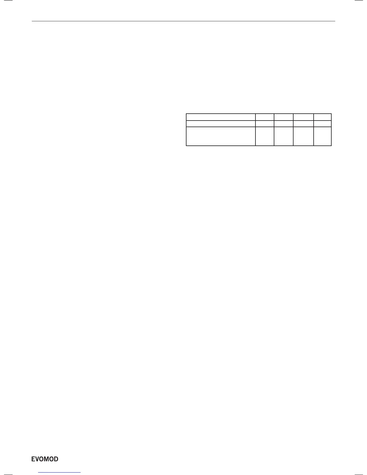
See table below for approximate maximum straight ue length.
Boiler 250 500 750 1000
Flue Size (mm) Ø150 Ø250 Ø250 Ø300
Approx. max.
Straight Flue 28 80 32 56
Length (m)
The addition of elbows and their positions in the ue will have
a signicant effect on the maximum allowable ue and air duct
lengths. Consult with your ue supplier for detailed design work.
IMPORTANT NOTE.
If combustion air is drawn from within the boiler room,
ensure no dust or airborne debris can be ingested into the
appliance. Dusty concrete ooring should be sealed to
reduce the presence of dust. Ideally where possible duct the
air supply into the boiler room from a clean source outside
the boiler room / building.
Material
With no requirement for buoyancy to discharge ue products
and with low ue gas temperatures, single wall ues are suitable
for most installations. Care should still be taken to maintain
compliance with building regulations and relevant standards.
The ue used should be a suitably approved ue for use on a
pressurised condensing ue system. The boiler is not suitable for
use on plastic ue systems.
Condensate produced in the ue should be drained
seperately before entering the boiler. A Drain point at the
bottom of the ue header (500, 750 and 1,000) is provided for this
purpose.
Advice regarding the availability of proprietary types of ue
system can be obtained by contacting Ideal Boilers.
All joints or connections in the ue system must be impervious
to condensate leakage. Low points in the ue system should be
drained using pipe of material resistant to condensate corrosion.
All drains in the ue should incorporate a water trap.
Care should also be taken in the selection of ue terminals as
these tend to accentuate the formation of a plume and could
freeze in cold weather conditions.
Care should be taken to ensure the specication of the chimney
is suitable for the application by reference to the manufacturers
literature.
NOTE:- Long Flues
It is recommended that a support bracket is tted at least every
1m of ue length and a bracket must be tted at every ue joint to
ensure ue seal and alignment of ue.
5
- Installation & Servicing

 Loading...


