WATER CIRCULATION SYSTEM
A circulation pump MUST be connected to the boiler, see below.
The boiler must NOT be used for direct hot water supply. The hot
water storage cylinder MUST be of the indirect type.
Single feed, indirect cylinders are not recommended and MUST
NOT be used on sealed systems.
The appliances are NOT suitable for gravity central heating nor
are they suitable for the provision of gravity domestic hot water.
The hot water cylinder and ancillary pipework, not forming part of
the useful heating surface, should be lagged to prevent heat loss
and any possible freezing - particularly where pipes run through
roof spaces and ventilated underoor spaces.
The boiler must be vented. There must be no low points between
the boiler ow connection and a system vent point, which should
be positioned as close as practically possible to the boiler ow
connection.
Draining taps MUST be located in accessible positions, which
permit the draining of the whole system - including the boiler
and hot water storage vessel. They should be at least
1
/2" BSP
nominal size and be in accordance with BS. 2879.
The central heating system should be in accordance with the
relevant standards listed on page 4.
Due to the compact nature of the boiler the heat stored within the
heat exchanger at the point of shutdown of the burner must be
dissipated into the water circuit in order to avoid overheating. In
order to allow pump operation after burner shutdown the boiler
control box incorporates a 2 minute pump overrun facility. In
order to make use of this, a pump must be controlled via the
terminals inside the boiler. (Refer to Frame 22).
Independent module pumps or valves may be tted where
hydraulic isolation is required. These must be wired to the
module pumps control terminals in the installation box. When
sizing module pumps refer to the water ow rates for the 250kW
model. When sizing a module value, take into account any
additional hydraulic resistance when sizing the system pump.
When sizing pumps, reference should be made to the Hydraulic
Resistance Table on page 6 which show the boiler resistance
against ow rates, to achieve the required temperature differential.
Flow rates for common systems using a 20
o
C temperature
differential are given in the table below.
Water ow rate temp.difference 20
o
C (36
o
F)
l/s m
3
/h
250 3.0 10.7
500 6.0 21.5
750 9.0 32.2
1000 12.0 43
Note.
• With the boiler ring at maximum rate, the temperature
differential should not be less than 20
o
C.
• With the boiler ring at minimum rate, the temperature
differential should not be greater than 35
o
C. Lower ow rates
generating higher temperature differentials will lead to poor
system performance.
• The lower the return temperature to the boiler, the higher the
efciency. At return temperatures of 55
o
C and below, the
difference becomes marked because the water in the ue
gases starts to condense, releasing its latent heat.
In installations where all radiators have been provided with
thermostatic radiator valves, it is essential that water circulation
through the boiler is guaranteed. A mixing header will perform
this task. Alternatively this can be best achieved by means of a
differential pressure valve, which is installed in a bypass between
the ow and return pipes. The bypass should be tted at least
6m from the boiler, and should be capable of allowing a minimum
ow rate to achieve a temperature differential of no greater than
35
o
C at minimum rate.
WATER TREATMENT
These boilers incorporate a STAINLESS STEEL heat
exchanger.
IMPORTANT. The application of any other treatment to this
product may render the guarantee of Ideal Boilers INVALID.
Ideal Boilers recommend Water Treatment in accordance with
Guidance Notes on Water Treatment in Central Heating Systems.
Ideal Boilers recommend the use of Fernox Copal or MB1
or GE Betz Sentinel X100 inhibitors and associated water
treatment products, which must be used in accordance with the
manufacturers' instructions.
For further information contact:
Fernox Manufacturing Co. Ltd., Cookson Electronics,
Forsyth Road, Sheerwater, Woking, Surrey, GU21 5RZ
Tel: +44 (0) 1799 521133
or
Sentinel Performance Solutions.,
The Heath Business & Technical Park,
Runcorn, Cheshire, WA7 4QX
Tel: 0800 389 4670. www.sentinel-solutions.net
1. It is most important that the correct concentration of the water
treatment products is maintained in accordance with the
manufacturers' instructions.
2. If the boiler is installed in an existing system any unsuitable
additives MUST be removed by thorough cleansing.
3. In hard water areas, treatment to prevent limescale may be
necessary.
4. Under no circumstances should the boiler be red before the
system has been thoroughly ushed.
ELECTRICAL SUPPLY
WARNING. This appliance must be earthed.
Wiring external to the appliance MUST be in accordance with
the current I.E.E. (BS7671) Wiring Regulations and any local
regulations which apply. For Ireland reference should be made to
the current ETCI rules for electrical installations.
The point of isolation from the mains should be readily accessible
and adjacent to the boiler.
CONDENSATE DRAIN
Condensate drains are provided on the boiler. These drains must
be connected to a drainage point on site. All pipework and ttings
in the condensate drainage system MUST be made of plastic - no
other materials may be used.
IMPORTANT. Any external runs must be insulated to avoid
freezing in cold weather causing blocking. (Refer to Frame 20)
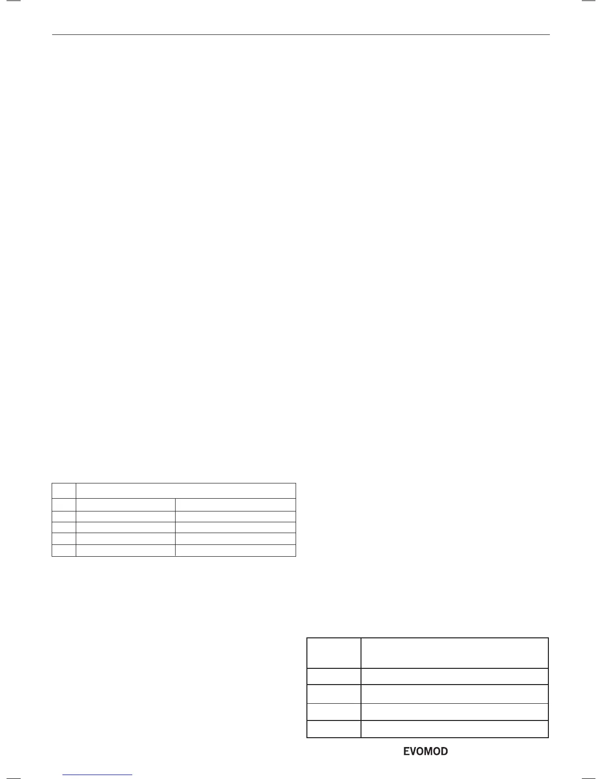
Boiler Pressure Drop
(mbar) @ 20
o
C Differential
250 410
500 410
750 410
1000 410
HYDRAULIC RESISTANCE -
6
- Installation & Servicing

 Loading...


