34
INITIAL LIGHTING
1. Check that the system has been lled and the boiler is
not air locked - air in the boiler could damage the heat
exchanger. For this reason if an automatic air vent has
been tted it must never be off.
2. Check that all the drain cocks are closed and any valves in
the ow and return are open.
3. Check that the GAS SERVICE COCKS ARE OPEN.
4. Check the indication on the pressure gauge. If the pressure
is less than 0.8 bar the installation should be lled up rst
(sealed system only).
5. Switch the electricity supply ON to all modules and check
that all the external controls are calling for heat. Check that
the boiler is in On Mode (see Frame 28).
6. The header pump switches on and the rst module fan
switches on. After 2 mins the rst module will ignite and
then the burner will modulate to satisfy the heat demand.
Additional modules will be switched on at regular intervals.
If after 5 attempts the module has failed to light then it
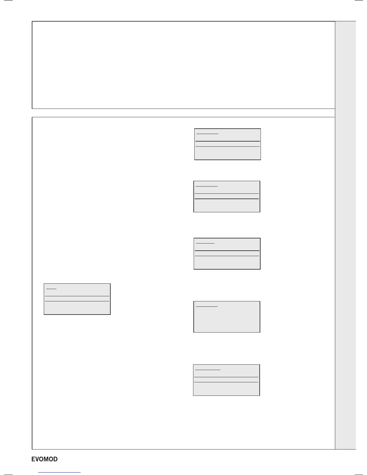
will lock out. To restart the Ignition sequence press the
reset button and a screen similar to the following will be
displayed.
Rotate the knob until the module you wish to reset is
highlighted and then press reset again.
7. The gas valves are preset at the factory to nominal values.
Dependant on site installation conditions (e.g. ue length)
the module performance can vary slightly. To check the
performance, measure the CO/CO
2
values at maximum and
minimum rates whilst adjusting the gas valves if necessary.
To set a module to run at either maximum or minimum rate
for 5 minutes press SELECT and the following screen will
appear.
Rotate the knob clockwise until a screen similar to the
following is displayed.
Press SELECT and a screen similar to the following will be
displayed.
Rotate the knob until Service is highlighted and press
ENTER and a screen similar to the following will be
displayed.
Rotate the knob until service for the appropriate module is
highlighted and press ENTER and a screen similar to the
following is displayed.
Rotate the knob until Minimum or Maximum is highlighted
as required and press ENTER.
8. Operate the boiler for 5 minutes and check the gas rate
(Table 1). You should obtain a value at least 90% of the
nominal.
9. Ret the module cover. See Frame 14.
33
COMMISSIONING AND TESTING
A. ELECTRICAL INSTALLATION
1. Checks to ensure electrical safety should be carried out
by a competent person.
2. ALWAYS carry out the preliminary electrical system
checks, i.e. earth continuity, polarity, resistance to earth
using a suitable meter.
WARNING. Whilst effecting the required gas soundness test and purging air from the gas
installation, open all windows and doors, extinguish naked lights and DO NOT SMOKE.
B. GAS INSTALLATION
1. The whole of the gas installation, including the meter,
should be inspected and tested for soundness and then
purged in accordance with the recommendations of the
relevant standards listed on page 4.
In IE refer to I.S.820:2000.
Reset
Normal Operation
Reset Module 1 01
Ideal 750kW
Normal Operation
Set Flow Temp
Set ON/OFF
Ideal 750kW
Set Flow Temp
Set Off/On
State of Inputs
State of outputs
Set Off/On
Off Mode
On Mode
Service
Service Mod 1
Off
Minimum
Maximum
Service Mod
Normal Operation
Service Mod 1
Service Mod 2
Service Mod 3
INSTALLATION
31
- Installation & Servicing

 Loading...


