(
(
32
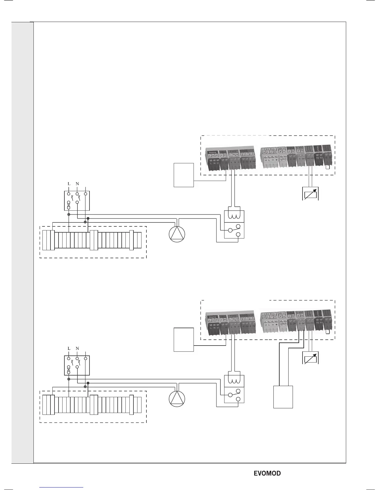
EVOMOD WITH SWITCHED LIVE OR 0-10V CONTROL
Note: that the boiler requires a 2 minute pump overrun period.
The boiler warranty will be invalid if this is not provided.
It is recommended that the pump overrun functionality is
achieved by connecting the pump to the boiler Header Pump
connections via a relay (see diagram).
Notes
1 The boiler will automatically congure itself to a Switched Live input
2 The Switched Live must be from the same phase as the boiler mains supply or be a volts free relay contact fed with 2 wires
from the Installer Wiring Box
EVOMOD WITH SWITCHED LIVE CONTROL
EVOMOD WITH 0-10V CONTROL
Note that the boiler must be congured for a 0-10V Input (see frame 28)
Installer Wiring Box
Master PCB Box
Master PCB Box
Feed from Mains
Circuit Board
Fused
Spur
Header Sensor
(Provided with Boiler)
Header Sensor
(Provided with Boiler)
Note
The MCB and wiring must be sized depending upon the total load requirement of the boiler plus any locally supplied pumps.
Switched
Live
External
Controls
Header
Pump
Relay
External
To Boiler
Installer Wiring Box
Header
Pump
Fused
Spur
Relay
External
To Boiler
Switched
Live
External
Controls
External
Controls
0-10V
Input
Feed from Mains
Circuit Board
+ -
INSTALLATION
30
- Installation & Servicing

 Loading...


