40
SERVICING SCHEDULE
To ensure the continued safe and efcient operation of the
appliance it is recommended that it is checked at regular
intervals and serviced as necessary. The frequency of
servicing will depend upon the installation condition and usage
but should be carried out at least annually.
Ideal Boilers does not accept any liability resulting from
the use of unauthorised parts or the repair and servicing of
appliances not carried out in accordance with the Company's
recommendations and specications.
Note.
Some build-up within the heat exchanger assembly is quite
usual with this type of condensing boiler. Though removal
and cleaning is recommended annually, the heat exchanger
and condensate trap must be inspected and cleaned after a
maximum of 2 years operation.
1. Light the boiler and carry out function checks, noting any
operational faults.
2. Run the boiler for 5 minutes and then check the gas
consumption rate. Refer to Frame 34 for reference on how
to force the burner to maximum and minimum rates.
3. For correct boiler operation the CO/CO
2
ratio of the ue gas
on each module should not be greater than 0.004 ratio and
the CO
2
values should be correct to the gures in Table 1
on Page 2.
4. If the combustion reading is greater than the acceptable
value AND the integrity of the combustion circuit seals and
ue system have been veried, and the gas inlet pressure
has been checked.
5. Remove and inspect the fan/venturi assembly. Refer to
Frame 45.
6. Remove the burner assembly and inspect the electrodes
and sightglass. Refer to Frame 46.
7. Remove and clean the burner. Refer to Frame 46.
8. Inspect the heat exchanger through the burner opening.
If there are signs of oxide build up, clean the exposed heat
exchanger surface with a suitable brush. Refer to Frame
47.
9. Clean the condensate traps. Refer to Frame 48 & 49.
10. Check that the ue terminal and air inlet are unobstructed
and that the uing and ducting are correctly sealed.
REPEAT PROCEDURE FOR BOTH SLAVE AND MASTER
MODULES.
11. After servicing refer to Frame 39 for nal safety checks.
41
GAS VALVE ADJUSTMENT
Maximum rate adjustment
1. Switch the boiler on and operate for 5 minutes.
2. See Table 1, Page 2 for minimum and maximum gas rate
setting.
3. Set the module to maximum output (see Frame 34).
4. Connect a suitable ue analyser to the ue sampling point of
the Master Module.
5. Using the maximum rate adjustment screw, adjust the
master module gas valve, if necessary, until the CO
2
measures 9.1% ± 0.2 (nb. clockwise reduces CO
2
).
6. Connect a suitable ue analyser to the ue sampling point of
the Slave Module.
7. Using the maximum rate adjustment screw, adjust the
Slave Module gas valve until the CO
2
measures 9.1% ± 0.2
(nb. clockwise reduces CO
2
).
8. Repeat until all modules are set at max.
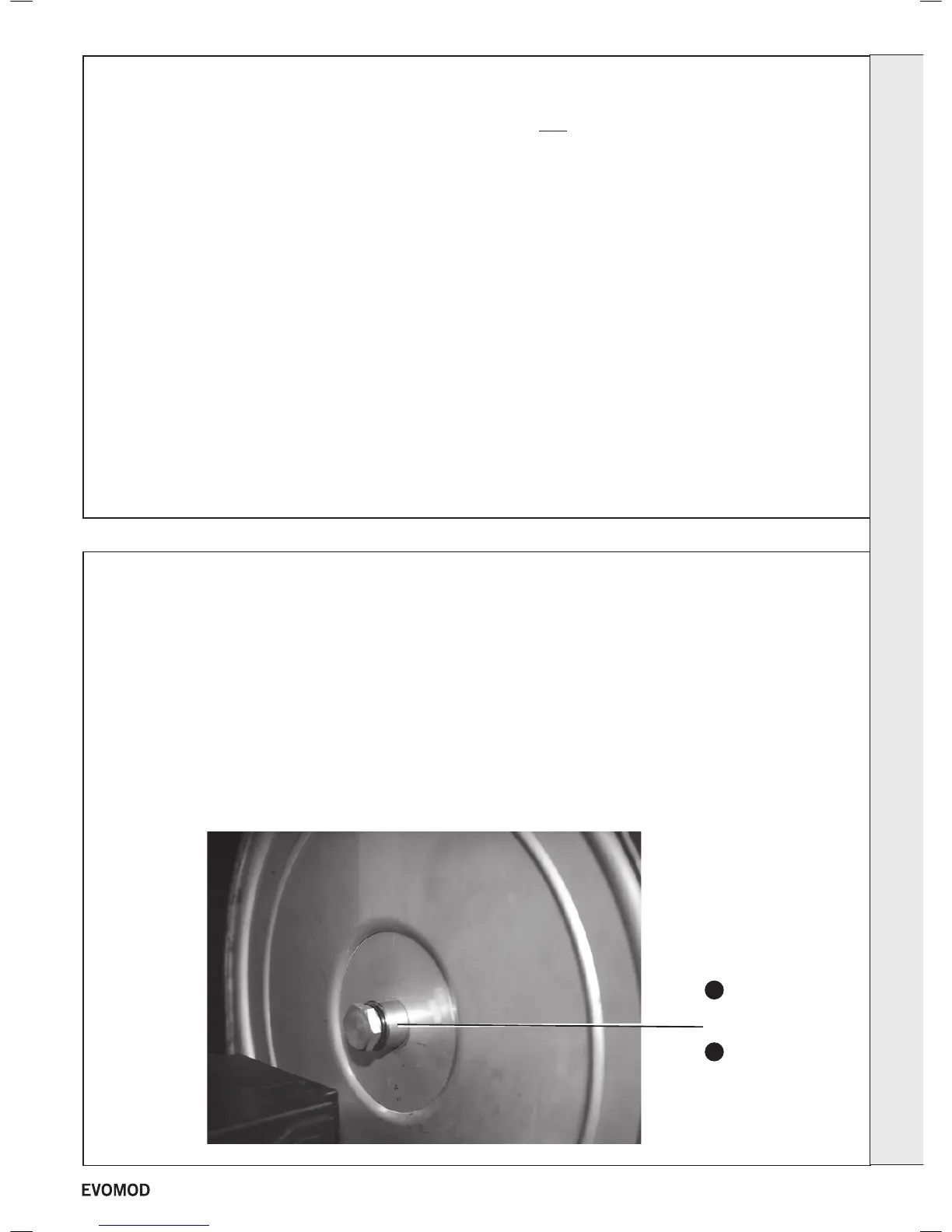
Flue sampling
point
4
11
If the boiler contains more than 1 Module tted with individual gas valves. All gas valves must be adjusted independently.
continued ..........
SERVICING
35
- Installation & Servicing

 Loading...


