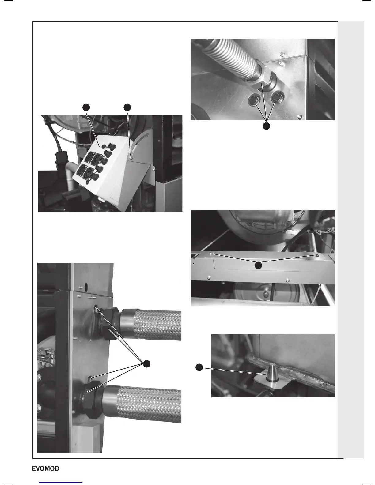
NB. Ignore items 5 and 6 for slave modules
1. Refer to Frame 40.
2. Remove the module front cover (refer to Frame 44).
3. Remove the right hand side panel (refer to Frame 15).
4. Isolate the water circuit and drain boiler.
5. Disconnect all ‘plug in’ connections to the junction box.
6. Slacken the mains wiring box xing screw and swing the
box down.
7. Remove the fan assembly (Refer to Frame 45).
8. Remove the burner assembly (Refer to Frame 46).
9. Remove the single xing bolt at the module water ow and
return connections and unscrew the union connections.
10. Remove the two xing bolts at the gas connections and
unscrew the gas union connections.
11. Pull the gas pipe forwards to remove.
12. Remove the water pressure switch and ow and return
thermistor electrical connections (Refer to Frames 56 &
57).
13. Disconnect and remove the heat exchanger condensate
debris collector (Refer to Frame 48).
14. Remove the two screws retaining the central frame inll
panel and remove panel.
15. Pull the heat exchanger unit forwards and lift off from the
support pins (the unit is heavy therefore ensure the safe
handling instructions contained on page 4 are followed).
16. Remove ow & return headers and t to new heat
exchanger.
17. Remove the water pressure switch and the return
thermistor and t to new heat exchanger.
18. Re-assemble in reverse order.
19. Re-ll the system ensuring all the air in the boiler is vented.
20. Refer to Frame 39 for nal safety checks.
65
HEAT EXCHANGER REPLACEMENT (MASTER & SLAVE MODULES)
5 6
10
14
15
9
SERVICING
47
- Installation & Servicing

 Loading...


