(C) IDM ENERGIESYSTEME GMBH
.
escriptio
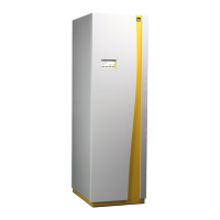
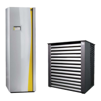
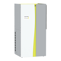
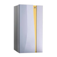
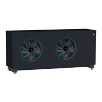
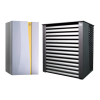
Installation instructions iPump A 2-7, 3-11
12
Description
Montage Heizungsseitig
Heat pump type iPump A 2-7 iPump A 3-11
Unit
Maximum heating supply temperature
6
°C 62
Regrigerant - R410A
Quantity of refrigerant (up to 6 m) kg 3.2 4.1
GWP
5
1924
Compressor oil - FV50S
EMKARATE
RL 32-3MAF
Quantity of compressor oil l 0.35 0.99
Compressor stages - 1-stage modulated
Air volume outdoor unit
(A7°C/W35°C at nominal speed
6
)
m³/h 2500 3600
Integrated loading pump Wilo Yonos Para RS15/7.5
Nominal fl ow rate heating water (A7°C/W35°C nom. speed) m³/h 0.8 1.2
Free residual pressure loading pump (A7°C/W35°C max. speed
*
) kPa 65 66
Free residual pressure loading pump (A7°C/W35°C nom. speed
*
) kPa 36 40
Pressure loss heating side (A7°C/W35°C) at nominal output
7
kPa 9 9
Connection dimension
Heating supply / -return
R
1“
Refrigerant pipe - Hot gas line mm Ø12.7x0.8(1/2“) 16
Refrigerant pipe - Liquid line mm Ø9.53x0.8 (3/8“) 12
Maximum length of split-piping between indoor- and outdoor unit m
20 m /
max. height diff erence 10 m
4
Electrical data
Electrical power supply compressor
V / Hz 1~230 / 50 1~230 / 3~400
Electrical power supply heating unit V / Hz 3~400 / 50 3~400 / 50
Electrical power supply controller V / Hz 1~230 / 50 1~230/ 50
Maximum operating current of compressor A 15.8 9 / 24
Maximum operating current of ventilator A 0.24 0.5
Maximum power consumption ventilator W 56 113
Performance factor cos phi 1 0.98
Maximum power consumption heating unit A 26 13.04
Starting current A < 15.8 < 9
Performance factor 1~230 V cos phi 0.99 0.97/0.99
Fuse of main power supply A C/K 16 C/K 13 / 25
Fuse of control main supply A B/Z 13 B/Z 13
Fuse electrical heater A B/Z 13 B/Z 13
1
Uncertainty of measurement ± 1,5 dB(A)
2
If the size of the installation room is lower then the required minimum size, the room must be performed as an engine room according to EN 378
3
12°C cold water temperature / 58°C buff er temperature
4
12°C cold water temperature / 75°C buff er temperature
5
According to the 5th IPPC Status Report
6
The 62°C refers to the maximum heat pump fl ow temperature. The resulting lower hot water temperature must be checked in relation to compliance with the drinking water
ordinance.
7
at 80% pump capacity
*Adjustment min. speed loading pump 60%, max. 100%