(C) IDM ENERGIESYSTEME GMBH
Installation instructions iPump A 2-7, 3-11
53
hydraulic diagrams
Ka
itel 11
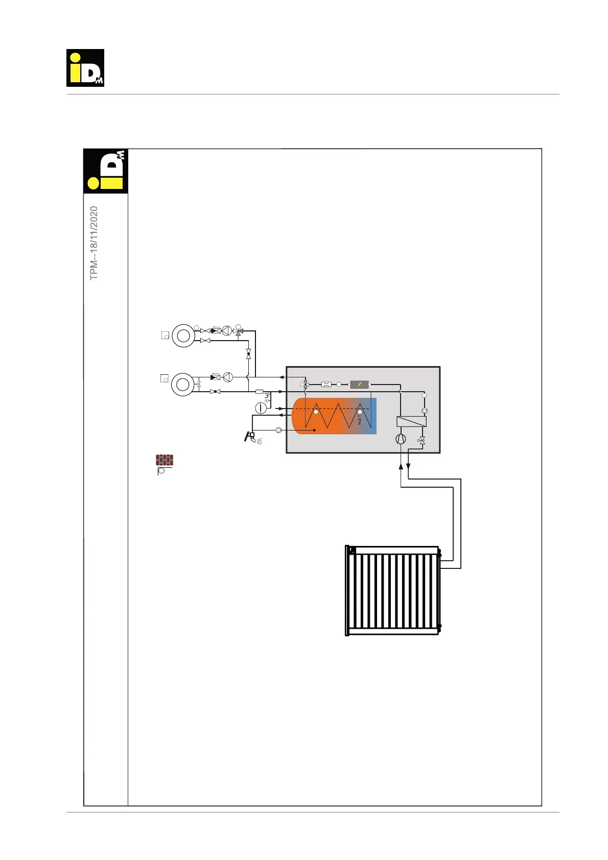
11.2. iPump A with direct heating circuit, hot water circulation and one mixer
heating circuit
B
A
T
T
T
T
T
T
T
M
T
P
TCE
FIL
L1.1-0-0-0-4
M
7
B
4
3
B4
3
6
3
4
5
6
Note: This is only a tentative suggestion for installing an IDM heat pump in the heating system. This suggestion replaces no
professional planning of an executing companie! On part of IDM-Energiesysteme can no warrenty be taken concerning the
function of the whole system!
iPump A + Direct and mixer circuit for heatin
indoor unit
outdoor unit
HW
HC (B)
RE (B)
OS
Circulation
CW
Refrigerant pipes
RE (A)
HC (A)
FS
When zone valves and direct circuits are used, at least 25% of the
onen must remain permanently open. Exception: With the
NAVIGATOR Pro, all zones can be equipped with
actuators. The AVIGATOR control takes over the minimum opening
management.
This scheme is not suitable for the following application:
HK (B) heating (winter operation)
HK (A) cooling (summer operation)
The scheme may only be used for heating operation:
HK (A) heating Low temperature (underoor heating)
HK (B) heat high temperature (radiator)