(C) IDM ENERGIESYSTEME GMBH
.
ydraulic diagra
s
Installation instructions iPump A 2-7, 3-11
52
hydraulic diagrams
Kapitel 11
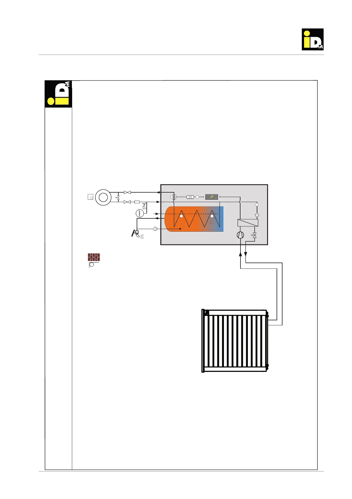
11. Hydraulic diagrams
11.1. iPump A with direct circuit for heating and hot water circulation
TPM--1
11
2
2
BA
T
T
T
T
T
T
TCE
P
FIL
L1.1-0-0-0-4
M
7
4
2
B
2
2
4
Note: This is only a tentative suggestion for installing an IDM heat pump in the heating system. This suggestion replaces no
professional planning of an executing companie! On part of IDM-Energiesysteme can no warrenty be taken concerning the
function of the whole system!
iPump A + Direct circuit for heatin
indoor unit
outdoor unit
HW
HC (B)
RE (B)
OS
Circulation
CW
Refrigerant pipes
When using direct heating circles and zone-valves, at
least 25 % of the zones have to be opened all the time.
Exception: With the NAVIGATOR Pro all zones can be
equipped with actuators. The NAVIGATOR control takes
over the minimum opening management.