(C) IDM ENERGIESYSTEME GMBH
.
ssembly a
d hydraulic i
stallatio
Installation instructions iPump A 2-7, 3-11
36
assembly and hydraulic installation
SL-Modul
pic.3
pic.4
pic.5
pic.6
Locking ring
pic.1
pic.2
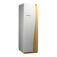
6.2. Replacement of the motor of the swit-
ching valve „Heating - hot water“
If the motor for the switching valve „Heating and hot
water“ has to be replaced, the side cover does not
have to be removed.
This allows easy corner installation on the right side
of the heat pump.
After the system has been disconnected from the
power supply, the front part must be removed fi rst and
the electric can be folded downwards.
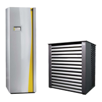
The switching valve with the motor is located in the
foamed buff er, seen from the front, on the upper right-
hand side (pic. 1).
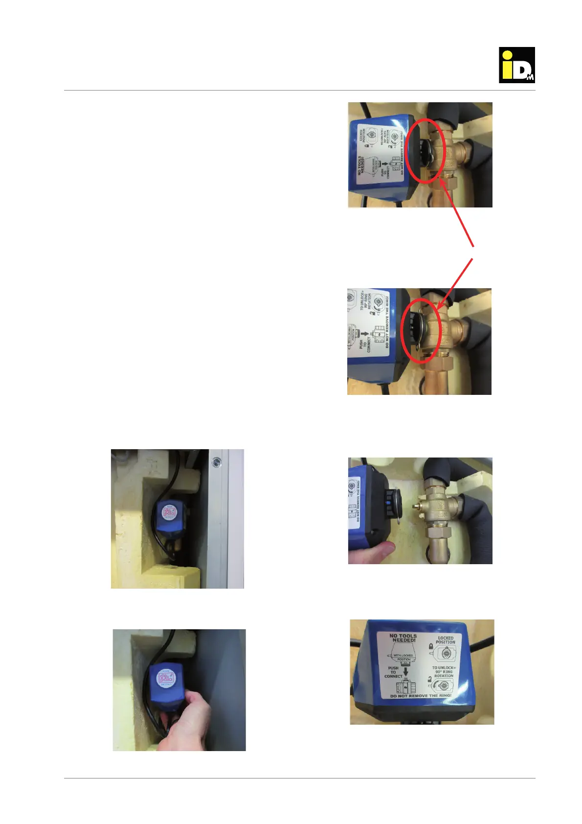
Now reach behind the motor with your right hand.
There you reach the locking ring, which holds the
motor at the switching valve (pic.2).
The circlip is now turned 90° downwards. This un-
locks the lock (pic.3, pic.4).
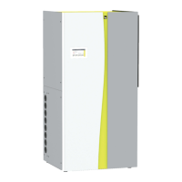
Now the motor can be pulled down to the front (pic.5).
Instructions for correct disassembly and assembly of
the motor are located on the motor housing (pic.6).