(C) IDM ENERGIESYSTEME GMBH
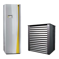
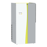
Installation instructions iPump A 2-7, 3-11
21
description
Monta
e Heizun
sseiti
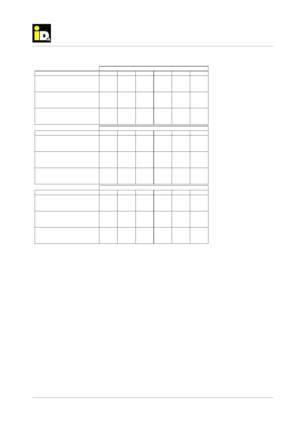
3.14. Cooling data detailed iPump A 3-11
40 35 30 25 20 15
Cooling capacity [kW] 10.90 10.99 10.98 10.90 10.97 10.98
Power intake 58.150.292.276.281.336.3]Wk[
29.543.567.411.454.300.3REE
Cooling capacity 43.969.875.891.808.724.7]Wk[
Power intake 05.165.136.117
.118.189.1]Wk[
22.657.572.597.423.457.3REE
Cooling capacity 39.328.327.306.305.393.3]Wk[
Power intake 95.026.056.096.047.008.0]Wk[
26
.651.686.512.537.462.4REE
40 35 30 25 20 15
Cooling capacity 87.0158.0148.0167.0111.0164.9]Wk[
Power intake 60.243.286.251.334.338.3]Wk[
42.546.440.424.359.274.2REE
Cooling capacity 30.856.762
.788.605.611.6]Wk[
Power intake 44.105.185.166.177.129.1]Wk[
65.580.516.441.466.391.3REE
Cooling capacity 41.330.339.228.288.219.2]W
k[
Power intake 85.016.066.017.018.049.0]Wk[
24.559.474.400.455.301.3REE
40 35 30 25 20 15
Cooling capacity 02.1145.0198.952.906.859.7]Wk[
Power intake 73.284.226.208.240.383.3]Wk[
27.452.487.303.338.253.2REE
Cooling capacity 39.655.671.68
7.504.520.5]Wk[
Power intake 93.154.125.116.147.119.1]Wk[
00.535.460.485.311.336.2REE
Cooling capacity 78.229.259.259.239.288.2]Wk[
Power intake
46.027.018.029.060.142.1]Wk[
05.470.446.302.367.223.2REE
&ůŽǁƚĞŵƉĞƌĂƚƵƌĞW7Σ
MAXNOMINAL
KƵƚĚŽŽƌtemperature [°C]
&ůŽǁƚĞŵƉĞƌĂƚƵƌĞW18Σ
MAXNOMINALMINMIN
&ůŽǁƚĞŵƉĞƌĂƚƵƌĞW12Σ
MAXNOMINALMIN
KƵƚĚŽŽƌtemperature [°C]
KƵƚĚŽŽƌtemperature [°C]
To guarantee a correct cooling mode, when working with unregulated direct-heating circles (without cooling
buff er) following 3 requirements have to be fulfi lled.
1. To ensure the minimum volume of heating site, appropriate zones have to remain open all the time.
Minimum volume 80 lt.
2. To ensure the minimum fl ow rate of heating site, appropriate zones have to remain open all the time.
Minimum fl ow rate 1.01 m³/h
3. To ensure the minimum cooling output rate of distribution system, appropriate zones have to remain open
all the time. The minimum cooling output rate is 70 % of the minimum cooling output power of the heat-
pump at A35°C/W18°C. Minimum cooling consumption 2.4 kW
All 3 requirements must be fulfi lled independently. This is possible via the Navigator Pro. The entire distribution
system has to fulfi ll the 3 mentioned requirements. To ensure a large cooling demand, the cooling limit has to
be set as high as possible.