(C) IDM ENERGIESYSTEME GMBH
Installation instructions iPump A 2-7, 3-11
33
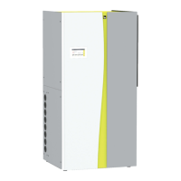
Internal side of the Front part with the cables
Although the fl exible hose with the cables
is long enough, it must be ensured that
during the removal of the front part the con-
nections in the electric pan or the control
unit do not pull out.
disassemble the ipump
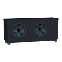
Außenlufteinheit
5.1. Connecting the control unit
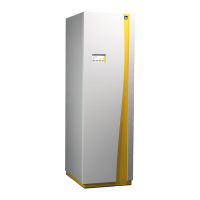
The control unit of the iPump is not connected on
delivery. The connecting cable to the control unit is
fi xed inside the front part by a cable strap.
The black cable is connected to the USB port. The
connection cables are inside of a fl exible hose. The
fl exible hose will be fi xed by a clamp for strain-relief
in the electric pan.
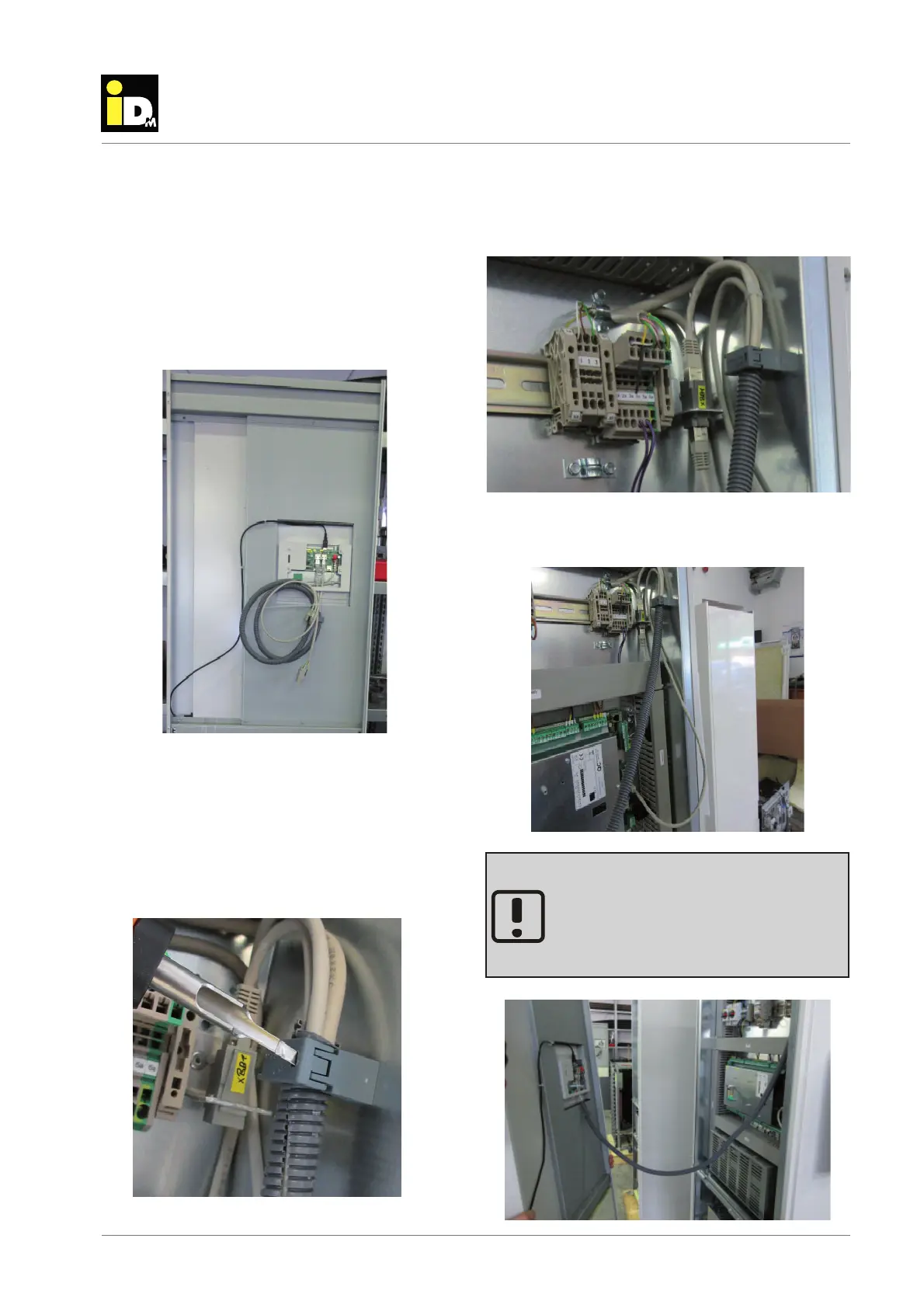
Before the cable will be pluged, the fl exible hose must
be fi xed in the strain-relief.
The clamp of the strain-relief can be opened with a
small tool kit.
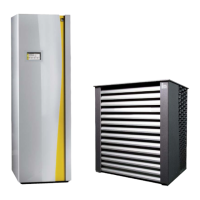
The individual connecting cables will be plugged in,
as shown in the photo below.
The LAN-cable can be placed in the cable channel.