(C) IDM ENERGIESYSTEME GMBH
.
isassa
ble the i
u
Installation instructions iPump A 2-7, 3-11
32
For the transport of the hot water tank and
the refrigeration equipment are no separa-
te handles or holders provided. To avoid
injuries, it is recommended to use gloves
for the transport.
Also it is recommended to use safety shoes
with corresponding protective caps.
After the iPump has been brought into the
boiler room, the assembly takes place in
reverse order.
disassemble the ipump
Außenlufteinheit
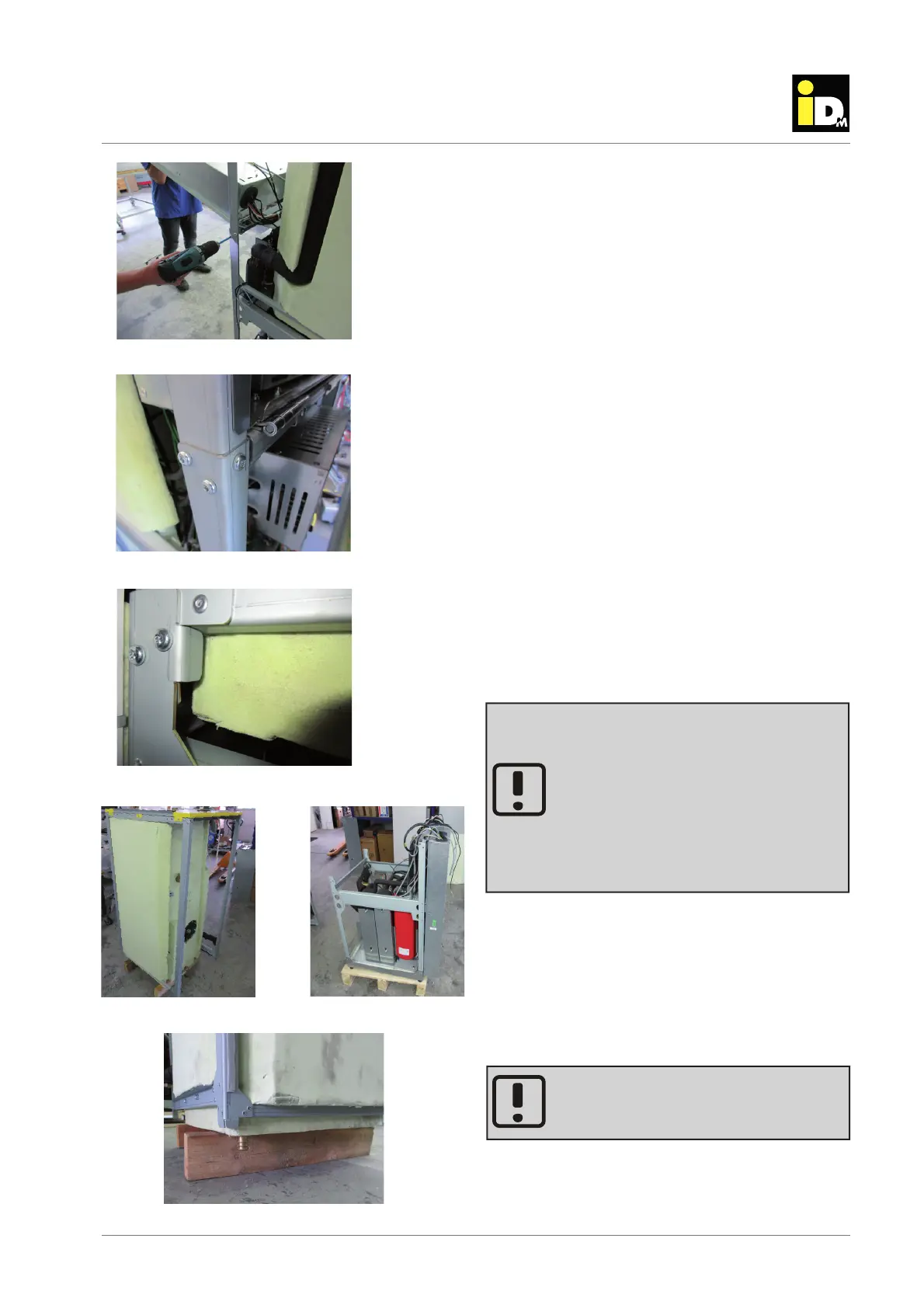
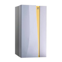
By loosing the connecting screws, the iPump can be
split. Thereby it is possible to transport the hot water
tank and the refrigeration equipment separately.
On the front side of the iPump base frame there are
six and on the back side are four connecting screws.
To loos the screws on the front side, the electric pan
must be lifted by a second person.
Once all connecting screws are loosened and remo-
ved, the hot water tank can be lifted down from the
refrigeration equipment. In order to avoid damage of
the connections, it is recommended to underlay two
timber beams under the hot water tank (see photo
below).
Connecting screws on the front side
Connecting screws on the back side
Refrigeration equipment
Hot water tank
Timber beams
Lift the electric pan