(C) IDM ENERGIESYSTEME GMBH
Installation instructions iPump A 2-7, 3-11
31
After the transport and the assembly of the
heat pump all connections must be resto-
red. All described sensors above must be
installed in the immersion sleeves.
disassemble the ipump
Außenlufteinheit
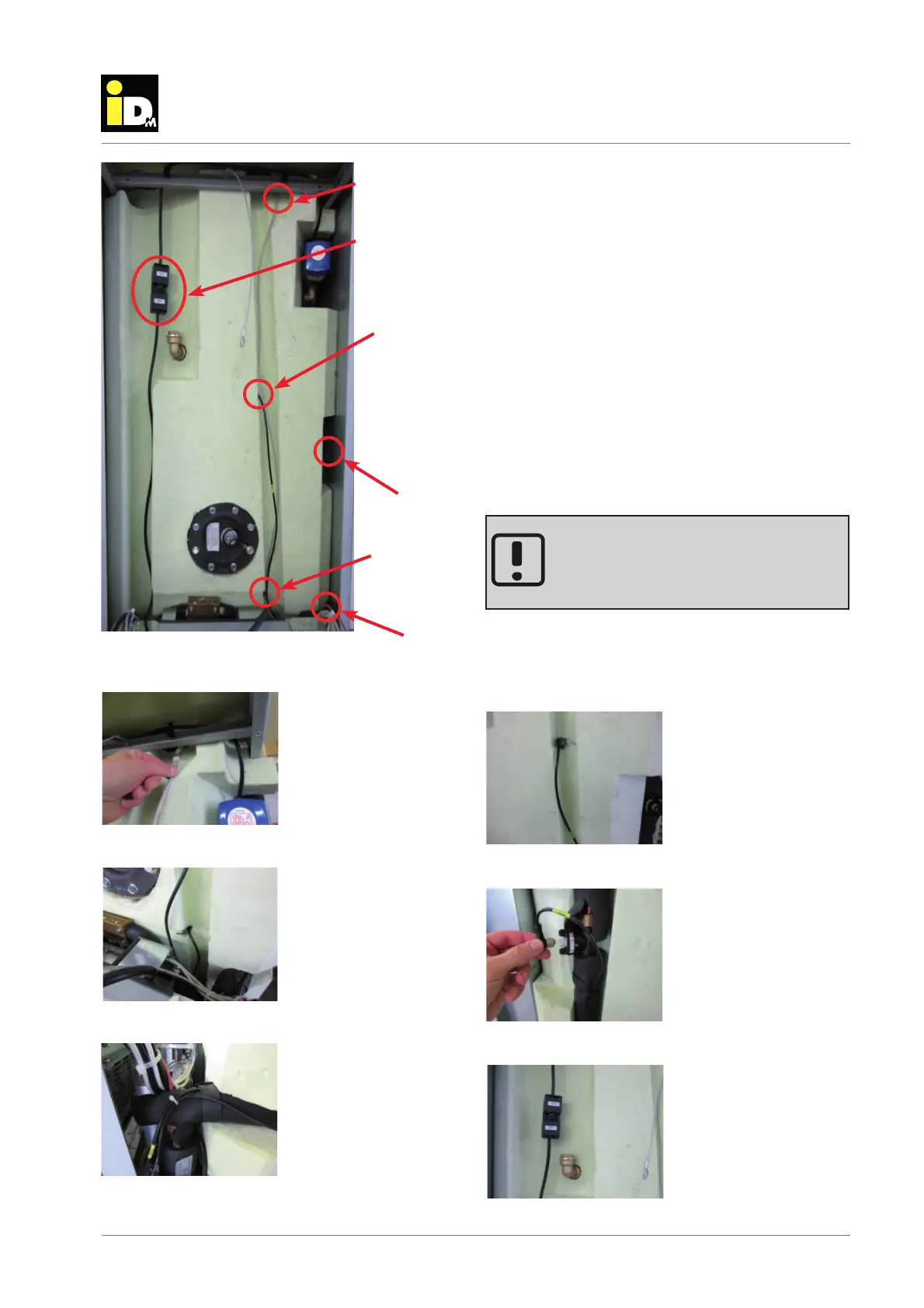
The electrical lines between the electrical pan and the
hot water tank must be disconnected.
The sensors B41 and B48 are mounted in the immer-
sion sleeve with a clip.
The sensor B33 is located under the Armafl ex insula-
tion. The sensor must be pulled out carrfully.
Also the connection cable to the fl ow rate transmitter
B2 and the LAN connection for myiDM must be dis-
connected.
The plug for the switching valve must be disconnec-
ted.
B48
B41
LAN connection
B2
B33
LAN connection
Hot water sensor B41
bottom area
Heat pump fl ow sensor
B33
Plug for switching
valve
Hot water sensor B48
Flow rate transmitter B2
Plug for switching valve