(C) IDM ENERGIESYSTEME GMBH
Installation instructions iPump A 2-7, 3-11
19
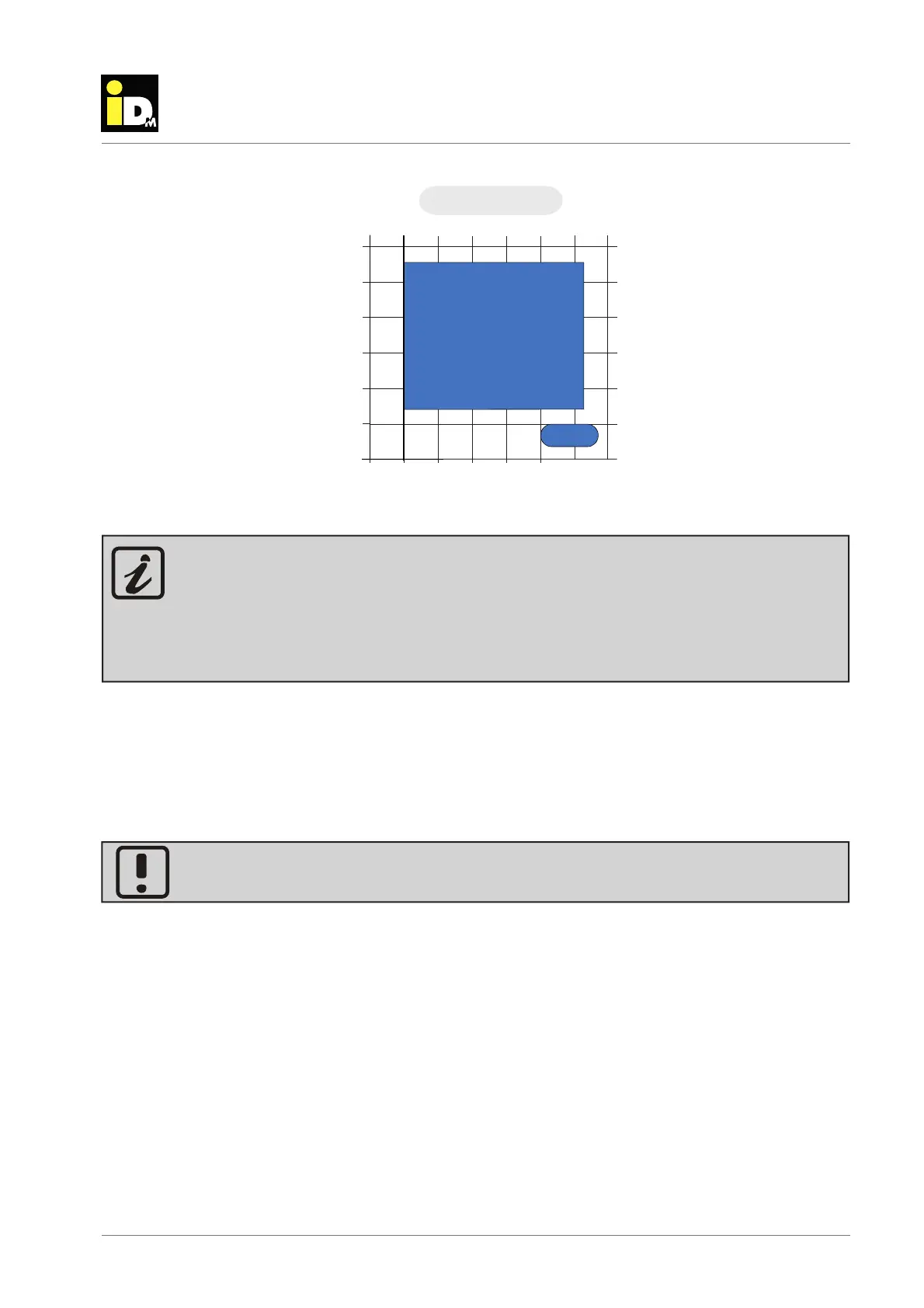
description
Monta
e Heizun
sseiti
10 15 20 25 30 35
10
15
20
25
30
5
[°C]
R410A
[°C]
40
45
0
Flow temperature
Outdoor temperature
iPump A 2-7 - Cooling
Cooling
The minimum heat pump fl ow temperature is the lowest temperature that the heat pump can produce
(depending on the heat source temperature) and is then switched off at this value. Due to the hydrau-
lic spread across the heat pump, the control-related switching hysteresis and the humidity-dependent
dew point, it is not possible to reach this temperature in the cooling circuit. The lowest possible
management temperature depends on the hydraulic design, the confi guration and the actual dew
point on site and is at least 5 K above the minimum heat pump fl ow temperature.
The maximum power of the iPump A can be limited with the NAVIGATOR 2.0 controller.