(C) IDM ENERGIESYSTEME GMBH
Installation instructions iPump A 2-7, 3-11
29
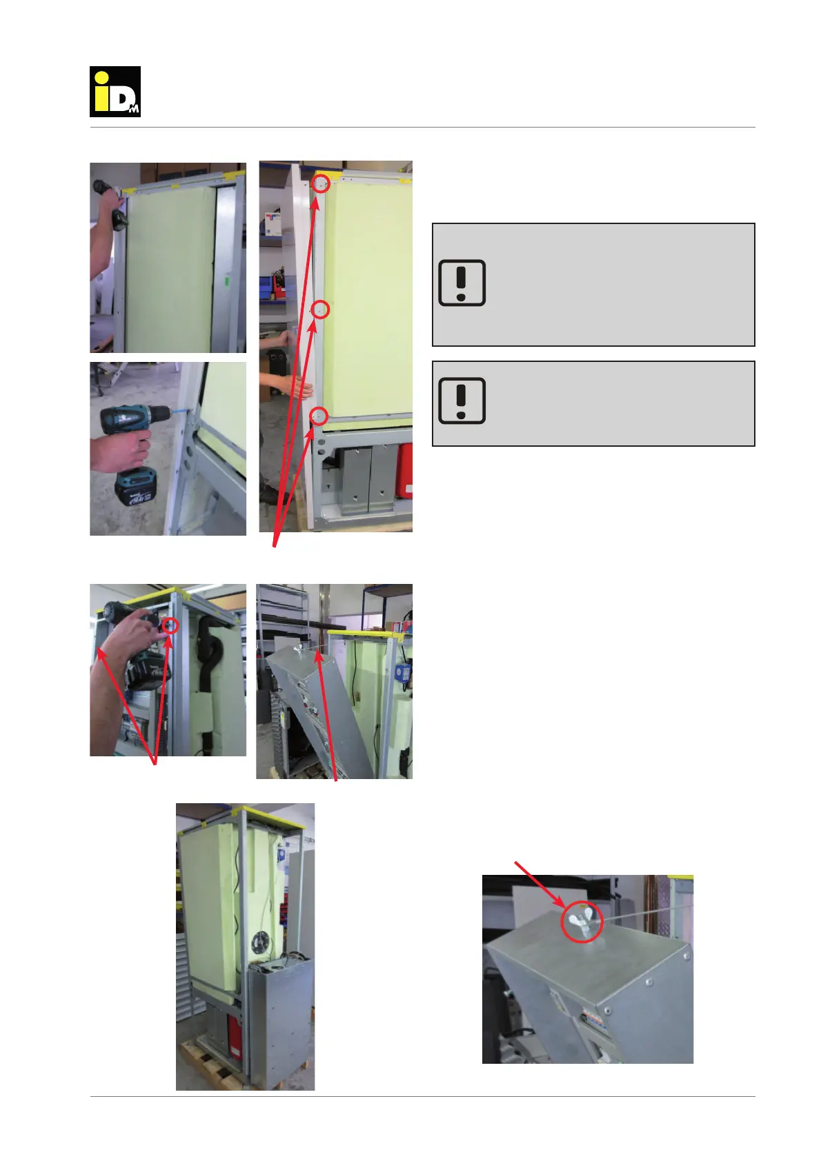
The rear panel is only fi xed to the base
frame by fi xing screws. Please observe that
the rear panel do not fall down when the
fi xing screws.
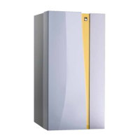
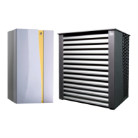
To assemble the indoor unit of the iPump in
the heating room, it is necessary that the
room has a minimum height of 2200 mm.
To the minimum height the dimensions of
the hydraulic piping and the tool must be
added.
disassemble the ipump
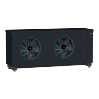
Außenlufteinheit
The rear panel is fi xed to the base frame by fi xing
screws. This screws must be loosened. After this, the
rear panel can be removed from the base frame.
At the front of the iPump, the electrical pan and the
main board are located above the refrigerating equip-
ment. The electrical pan can be hinge down when
loosing the fi xing screws.
The electrical pan is secured by a safety rope
against unintentional hinge down.
Anyway, ensure that the electrical pan does not
fall down when loosing the fi xing screws.
To loosen the safety rope, the locking nut must be
removed.
If the cover parts are removed, all hydraulic connec-
tion lines between the refrigeration equipment and
the hot water tank must be loosened.
Loos the fi xing screws
Loos the fi xing screws
Safety rope
Locking nut