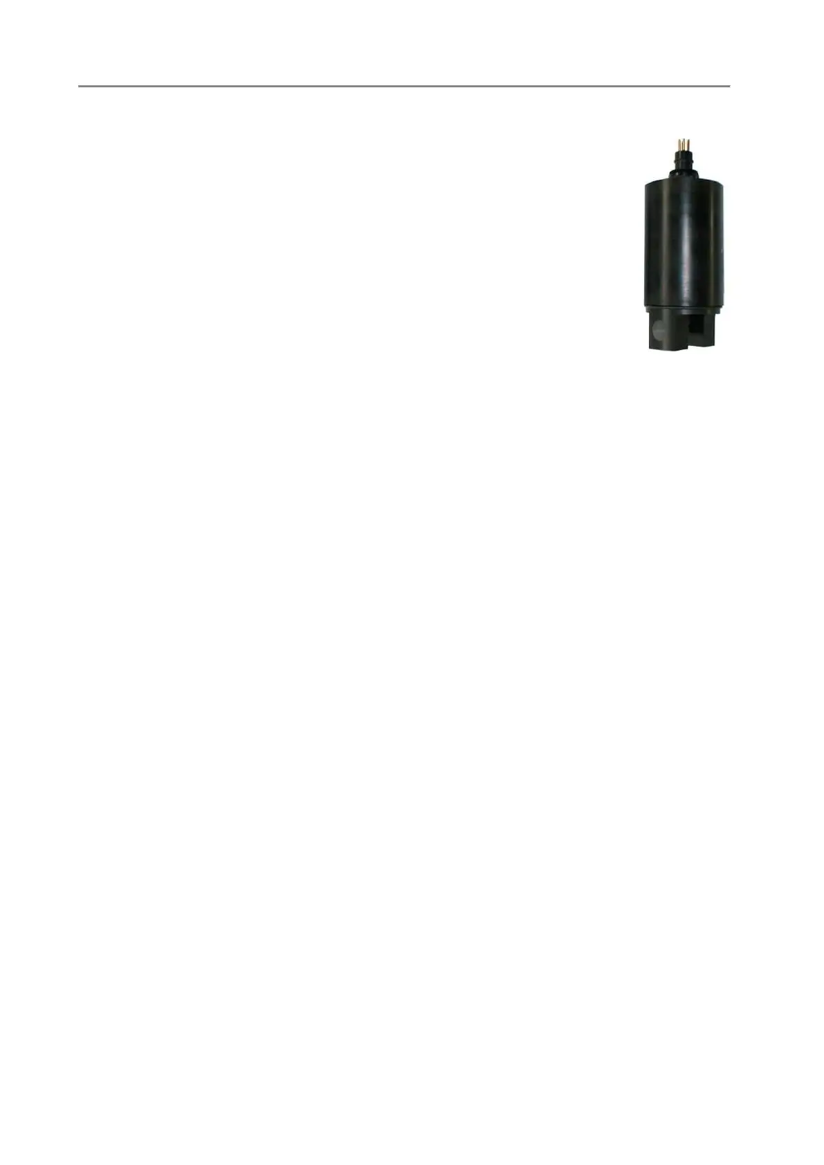
C4 SEAPOINT OEM FLUOROMETER
The SEAPOINT Fluorometer allows the user to monitor chlorophyll
concentration by directly measuring the amount of fluorescence emission from
a given sample of water. The sample media is pumped through a quartz tube
mounted through the long axis of the instrument. Chlorophyll, when excited
by the presence of an external light source, absorbs light in certain regions of
the visible spectrum and re-emits a small portion of this light as fluorescence
at longer wavelengths. SEAPOINT uses two bright blue LEDs (centred at 455
nm and modulated at 1 kHz) to provide the excitation. Blue interference filters
are used to reject the small amount of red light emitted by the LEDs. A
detector, positioned at 90
o
to the axis of the LED mounts, measures the emitted
light from the sample volume. The approximately 0.25 cm3 sample volume is
defined by the intersection of the excitation light with the field of view of the
detector, within the quartz flow tube. A red interference filter is used to
discriminate against the scattered blue excitation light. The red fluorescence
emitted at 90
o
is synchronously detected at 1 kHz by a silicon photodiode. The amplified and
demodulated voltage output of the photodiode is provided to the user for connection to a digital
voltmeter or an a-d converter. The calibration procedure is the same described for the turbidity meter.
The only differences are the measuring scales, which in the case of the fluorometer are: 5, 15, 50 and
150 µg/l.
C4.1 CONFIGURATION
The following parameters are requested to properly set up the SEAPOINT STF Fluorometer. The
sensor setup sequence can be run using the CNAP command available under the CONF menu
Logical code [0..255]:11
Description :Chl-a
Significant digits [1..13]:6
Digits after the dot [0..9]:2
Do you want to store it ?:Yes
Do you want to show data ?:Yes
Data processing method
0)Counts,1)mV,2)Custom&UNESCO,3)Polynomial,4)a+bx
Method [0..4]:2
Mux[0..7,240=A.Board,255=NU]:1
Compensate thermal drift ?:No
Fluorometer with multiple measuring scales ?:Yes
STF scales:1)>150,2)50,3)15,4)5
Startup scale [1..4]:1
Enable automatic scale selection ?:Yes
C4.2 CALIBRATION
The STF sensor is calibrated by entering an offset and slope for each measuring range. The procedure
can be run starting from the CASE command available under the CALB menu.
• Measuring scale 1, Full scale [150 ug/l]
• Measuring scale 2, Full scale [50 ug/l]
• Measuring scale 3, Full scale [15 ug/l]
• Measuring scale 4, Full scale [5 ug/l]
Measuring scale 1, Full scale [150]
Do you already know 'SLOPE & OFFSET' coefficients ?:No type [Y]es or [N]o < y